


34006451EN/AC - Page 19
installation
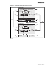
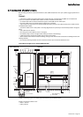
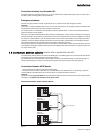
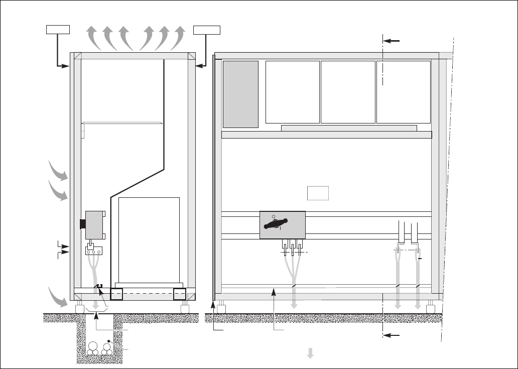
2.7 Connection of power circuits
Left cubicle of single-unit or parallel UPS with SSC
Before making connections, check that switches Q1, Q4S, Q3BP and Q5N are in the "open" position (toggle opposite the "O"
mark).
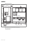
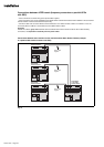
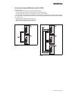
General:
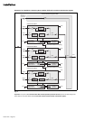
– in the case of parallel-connected rectifier-inverter cubicles with SSC, switches Q4S and Q3BP are not included and
mains 2 is connected to the Static Switch Cubicle. The other connections are the same;
– for modular UPSs with an external maintenance bypass, switch Q3BP must be locked open;
– the power cables for the connections between cubicles are not supplied;
– open the doors and remove the lower terminal shields (secured by screws to the cubicle chassis) of the rectifier-inverter
and Static Switch Cubicles;
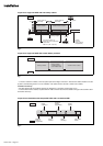
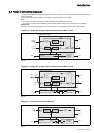
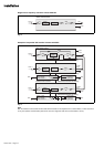
– connect the cables shown in heavy lines in the wiring diagrams shown previously to the terminals specified in the figures
below;
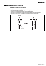
– each cubicle must be earthed;
– the routing of the power cables is shown in the figures;
– the auxiliary wiring is routed in troughs located nearby (not shown in the drawings);
– outside the cubicles, separate the auxiliary wiring from the power cables;
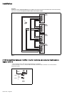
– all the cubicles must be interconnected for earthing, forming a mesh which is itself connected to the building structure and
earthing electrode;
– the connection drawings hereafter show the cubicles with doors open and terminal shields removed.
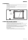
Cables connected by lugs to 100 x 8 mm copper terminals and 13 mm diameter holes.
Height of connections relative to floor:
– mains 1: 450 mm;
– battery: 480 mm.
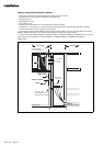
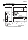
cross-section AA
front view
A
A
L1
L2
transformer
cable tie bar
mains 1
L3
battery
L+
L
rectifier
charger
inverter
stack
inverter
stack
inverter
stack
spacing
uprights
cable
tie bar
air extraction
air
admission
air
admission
connection
from below
trough (if applicable)
rearfront
mains 1
battery
power cable routing
via the bottom
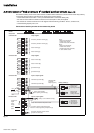
FHCZ
board
Q1
on
off