


34006451EN/AC - Page 30
Installation
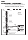
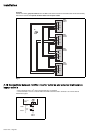
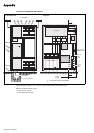
2.13 Connection of the "LED" remote indications unit
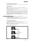
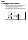
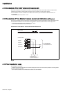
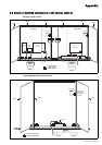
2.14 Connection of "Tele Monitor" remote control and indication unit
(option)
Connection of "Tele Monitor" remote control and indication unit
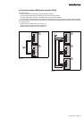
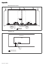
2.15 Final installation steps
This unit is connected to connectors XR1 and XR2 of the remote relay boards of the rectifier-inverter and Static Switch
Cubicles (see the location of these boards in the figures of the "connection of power circuits" section).
For the installation of the unit and details of connections at the unit end, see the instructions delivered with the unit
nr 5102990400.
– recommended cable cross-section: 1 mm
2
.
This unit is connected by means of a signal loop connecting the XR10 connectors of the RAUZ 1 boards of the rectifier-inverter
and Static Switch Cubicles to the unit connectors. These RAUZ 1 boards are located near the remote relay boards.
– recommended cable cross-section: shielded 0.4 mm
2
cables;
– consult manual 6739388XU for further information.
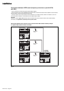
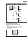
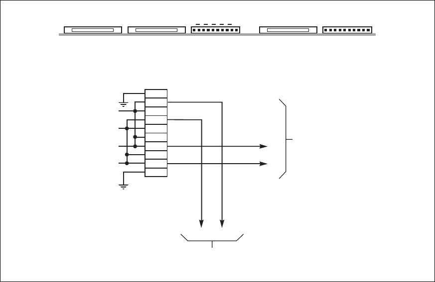
Fig. 26
After making the connections:
– install the front and rear base plates of the cubicles, clipping them to the feet of the cubicles (unless the connecting cables
are fed through these openings);
– refit the terminal shields of the terminal blocks, switches and circuit breakers.
connector XR10
reception
reception
+
transmission
transmission
+
to connector XR081
on the COMZ board
in the "Tele Monitor" unit
to connector XR10
of another rectifier-inverter
or static switch cubicle
RAUZ 1 board
1
2
3
4
5
6
7
8
9
10
XM097 XM096
1
10
XR11
XR10
XM098
2
4
97