


34006451EN/AC - Page 29
Installation
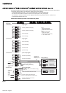
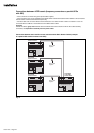
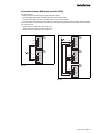
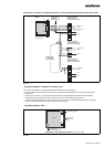
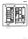
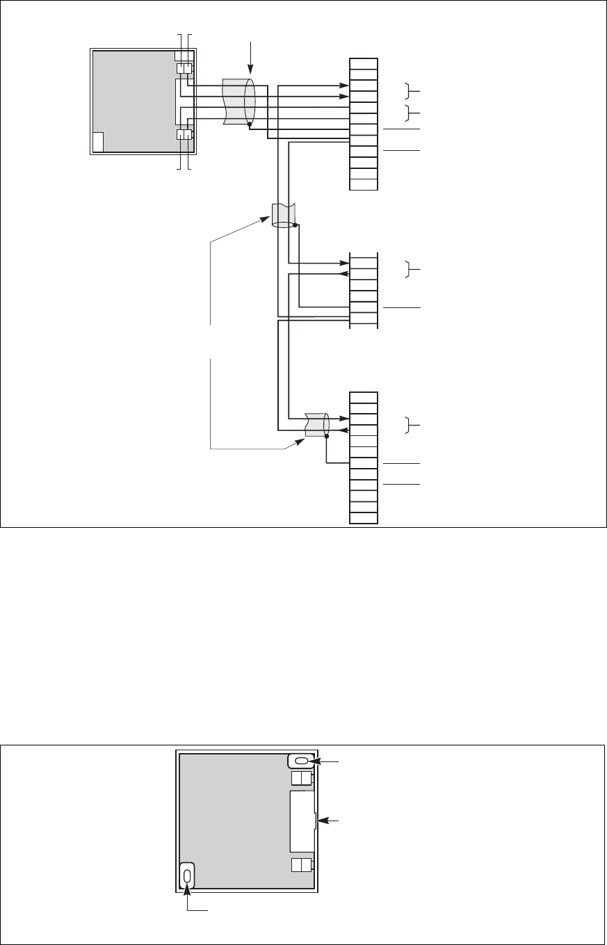
Connection of the battery "Temperature Monitor" (for a parallel UPS with batteries in the same room)
Fig. 24
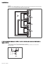
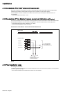
"Temperature Monitor" installation in a battery room
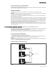
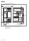
"Temperature Monitor" base
Fig. 25
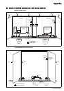
The "Temperature Monitor" should be secured against a wall or any vertical support:
– choose a location near the batteries and away from draughts which adversely affect the accuracy of temperature
measurements;
– position the unit correctly ("on" light in the top left hand corner and cable fed through from the right-hand side);
– use the holes provided in the base plate to screw the unit to the vertical support (see figure 25);
– unless the connecting cable runs on the surface, break the knock-out in the unit base plate provided for cable entry;
– secure the cable by suitable means so that it does not pull on the unit.
temperature
signal
earth
BC
BC +
temperature
signal
earth
NC
BC
BC +
remote relay board
connector XR4 on
rectifier-inverter cubicle 1:
1
2
3
4
5
6
7
8
9
10
11
12
battery "Temperature
Monitor"
XR2
XR1
(unit shown open)
12 +12
shielded cable
(2 twisted
telephone pairs)
3
4
5
6
7
8
remote relay board
connector XR4 on next
rectifier-inverter cubicle:
remote relay board
connector XR4 on nth
rectifier-inverter cubicle:
1
2
3
4
5
6
7
8
9
10
11
12
shielded cable
(1 or 2 twisted
telephone pairs)
temperature
signal
12V
+
12V
earth
NC
BC
BC +
power supply
BC+ BC
earth
earth
oblong holes
for fastening screws
knock-out for
lateral cable
entry
oblong holes
for fastening screws
board
dimensions of the "Temperature Monitor": 75 x 75 x 21 mm