


34006451EN/AC - Page 3
Contents
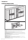
1. Characteristics
1.1 Characteristics common to all cubicles ............................................................................................ 4
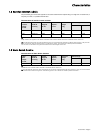
1.2 Rectifier-inverter cubicle .................................................................................................................... 5
1.3 Static Switch Cubicle ........................................................................................................................... 5
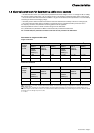
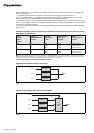
1.4 Electrical parameters for selecting protective devices ................................................................... 6
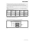
1.5 Electrical parameters for determining cable cross-sections .......................................................... 7
2. Installation (to be carried out by qualified personnel only)
2.1 Handing .............................................................................................................................................. 10
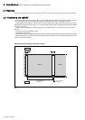
2.2 Positioning the cubicles .................................................................................................................. 10
2.3 Floor loads (figure 5) ........................................................................................................................11
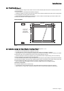
2.4 Cubicle layout on false floor or normal floor (figures 6, 7, 8) ........................................................11
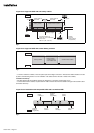
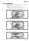
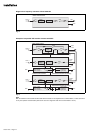
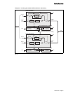
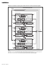
2.5 Power circuit wiring diagrams ......................................................................................................... 13
2.6 Cubicle mounting and connection ................................................................................................... 17
2.7 Connection of power circuits ........................................................................................................... 19
2.8 Connection of "Media Contacts 9" standard auxiliary circuits (figure 16) ................................... 22
2.9 Connections between cubicles (modular UPSs or parallel UPSs with SSC) .............................. 23
2.10 Connections between rectifier-inverter cubicles and external maintenance bypass cubicle .26
2.11 Connection of "Media Contacts 15" additional auxiliary circuits
(figure 22) ................................................................................................................................... 27
2.12 Connection of the battery "Temperature Monitor" (optional) ...................................................... 28
2.13 Connection of the "LED" remote indications unit ....................................................................... 30
2.14 Connection of "Tele Monitor" remote control and indication unit (option) .............................. 30
2.15 Final installation steps .................................................................................................................. 30
3. Appendix (to be carried out by qualified personnel only)
3.1 Mains 2 line protection ..................................................................................................................... 31
3.2 Cubicle mounting and connection for 2000 kVA Static Switch Cubicle ....................................... 32
3.3 Details of earthing connections in the various cubicles ................................................................ 35