


InRow RC Installation24
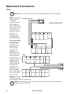
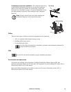
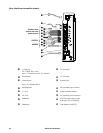
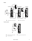
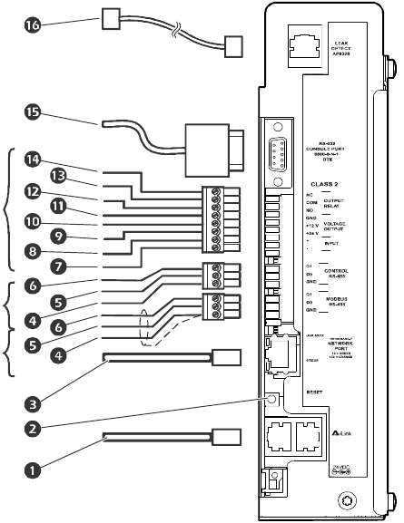
User interface connection pinout
1
A-Link port
Pin 1=High; Pin 2=Low;
Pins 3, 6=Perf Power; Pins 4, 5=Ground
9
24 Vdc (bias)
2
Reset button
:
12 Vdc (bias)
3
Network port
Pins 1-8 = Standard RJ-45
;
Return (bias)
4
Shield/ground
<
NO (normally open contact)
5
A-=True
=
COM (common contact)
6
B+=True
>
NC (normally closed contact)
7
Shutdown -
?
RS-232 console port (see the
InRow RC Service Manual)
8
Shutdown +
@
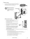
Leak detector (AP9325)
na1579a
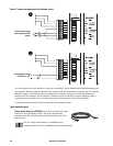
MODBUS
CONTROL
Shutdown input
contacts and alarm
output contacts