


ADSL 4-Port Ethernet USB Wireless-G Router User Guide
ADSL 4-Port Ethernet USB Wireless-G Router User Guide Page 13 of 52
3.2.2
Back Panel
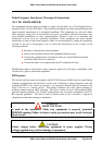
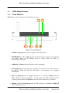
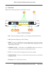
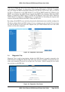
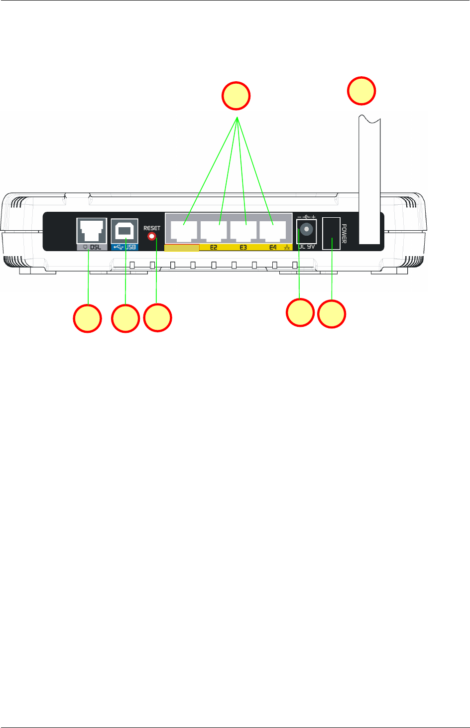
Fig 1-3 shows the back panel indicators of the Wireless-G router.
Figure 1-3 : Back Panel Indicators
1. DSL - Connect the telephone jack (RJ-11) to your Telephone Wall Socket (DSL line).
2. USB - Connect the USB jack to your PC’s USB slot.
3. RESET - To reset your ADSL Router to factory default settings (all customised settings
that you have saved will be lost!). To reset the ADSL Router, simply press the reset
button for about 10 seconds.
4. ETHERNET (E1-E4) - 10/100 Base-T Auto-MDI/MDIX Ethernet jack (RJ-45) to
connect to your PC’s Ethernet Network card or Ethernet Hub / Switch.
5. DC 9V - To connect to the Power Adapter that comes with your package.
6. POWER SWITCH - To power on or off the modem. Push downwards to switch ON and
lift upwards to OFF.
7. RF Antenna - 180° 2.4Ghz Wireless Antenna.
E1
1
2
3
5
6
4
7