


6
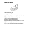
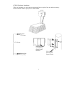
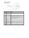
Controls and Indicators
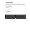
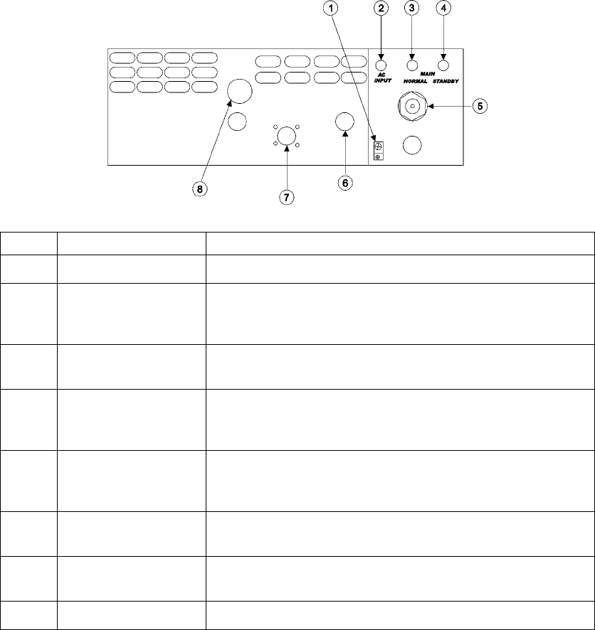
CTSLLP/G Bottom View
Index Control/Indicator Definition
1 Ground wire lug Provides connection of chassis to earth ground
2 Utility power input
indicator lamp (not
present on all models)
Yellow indicator illuminates when line voltage is present
3 Normal indicator lamp Green indicator illuminates when the unit is operating in normal
mode, (output is provided by CTFLM module)
4 Standby indicator
lamp
Red indicator illuminates when the power supply has transferred
from normal to emergency or backup operation, (usually
indicates loss of line voltage)
5 Entry point for utility
power conduit – ½”
(1.3 cm)
Physical entry point for utility power input wiring
6 Optional second
CTFLM cable adapter
Coax adapter used when an optional backup CTFLM module is
installed
7 Status monitoring
connector
Entry point for status monitoring connector
8 Output cable adapter Coax adapter for power supply output