


7
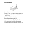
Wiring
Install an approved 20 A high-magnetic utility circuit breaker.
Ensure the utility circuit breaker is OFF.
• Unlock and open the front/top panel on the CTSLLP/G.
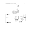
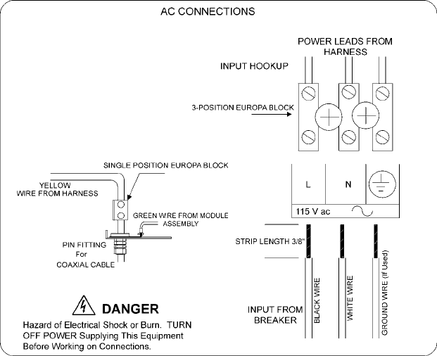
Refer to the diagram below for wiring details.
• Connect the black and white wires from the incoming utility line.
• Route the power feed coax to the bottom of the enclosure and attach to the coax cable
adapter using a pin connector.
• Attach the stinger lug to the pin connector center pin.
• Attach suitable solid copper ground wire to the enclosure ground lug and ground in
accordance with local codes.
• Check for voltages between each connector pin and ground using a multimeter.
Presence of voltage indicates an improper ground. If voltage is present ensure the
ground contact is secure.
• Reinstall the front/top panel on the CTSLLP/G.