


MX28B-1200 PRODUCT MANUAL Revision B
24 MX28B-1200/2400
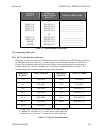
5.7.1 External Alarm Inputs
Four external alarm inputs with assignable priority levels are available. These alarm inputs
respond to external dry contact closures between normally open (NO) and common (C) or
contact openings between normally closed (NC) and C (see Table 5-1).
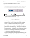
Table 5-1. External Alarm Input Definition
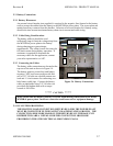
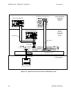
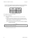
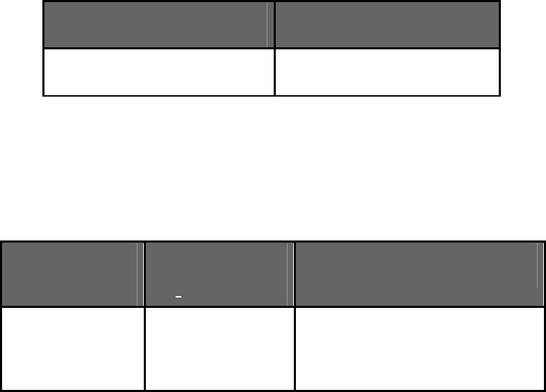
Table 5-2 shows the external alarm input connection designations. Connector J4 is located on
the alarm interface board mounted in the space above the control unit. Systems are shipped with
jumper wires connecting each NC and corresponding C contact. A jumper wire should be
removed only if the corresponding NC-C contacts are going to be used.
EXTERNAL
ALARM
INPUT
J4 TERMINAL
DESIGNATION
(NO-NC-C)
USER ALARM NOTES
#1
#2
#3
#4
NO1-NC1-C1
NO2-NC2-C2
NO3-NC3-C3
NO4-NC4-C4
___________________________
___________________________
___________________________
___________________________
Table 5-2. External Alarm Input Connections
5.7.2 Alarm Outputs
There are eight alarms available that provide outputs via Form “C” relay contacts. The last two
of these are pre-assigned as the Minor and Major alarm outputs. The Major relay is energized
(NO-C contacts closed) during normal (non-alarm) operating conditions; all the other relays
energize when an alarm condition occurs. The other six outputs are initially designated as
“Relay 1” through “Relay 6” (the user may assign more meaningful names if desired). The
various system alarm conditions can be assigned to any of the eight alarm outputs.
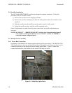
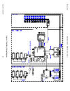
Table 5-3 shows the alarm output connection designations. Connectors J1 and J2 are located on
the alarm interface board mounted in the space above the control unit. The relay contacts should
only be used to switch resistive loads of 0.5 amperes or less at 60 volts or less.
External Alarm Source
(non-alarm state)
Connect To Input
Alarm Terminals
OPEN
CLOSED
NO-C
NC-C