


Revision B MX28B-1200 PRODUCT MANUAL
MX28B-1200/2400 27
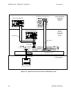
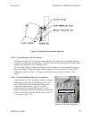
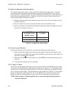
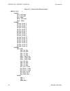
Figure 5-9 Plug-in Circuit Breaker Insertion
5.8.2.2 Circuit Breaker Load Connections
Connections for the -48V dc loads are located directly to the side of the corresponding breaker.
A typical load connection would utilize a #6 AWG wire with a two-hole lug on 5/8-inch centers,
attached with standard #10-32 mounting screws.
The load return cables for each circuit breaker section connect to a return bus directly opposite
the circuit breakers. These return buses contain patterns for 28 two-hole #10-32 lugs on 5/8-
inch centers, and 14 two-hole ¼”-20 lugs on a double-pattern of either 5/8-inch or 1-inch
centers.
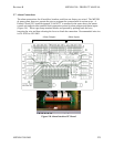
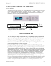
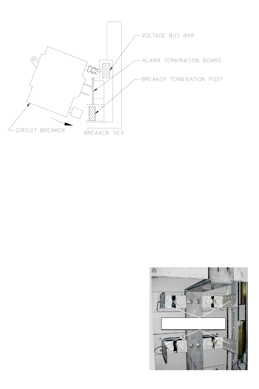
5.8.2.3 Power Distribution Fuse Load Connections
Connection for the –48V dc loads are made to L-shaped
landing pads connected to the distribution side of the
fuse. All the fuses within a given box frame have a
common bus connection to –48V dc. Load side
connections utilize a double-hole lug on 1 ¾ -inch
centers and return connections are made to the common
return bus bar at the top of the cabinet using 1-inch or 1
¾ -inch lugs (Figure 5-10).
Fuse Connections
Figure 5-10 Fuse Bay Connections