


Site Preparation & Installation Guide Universal Transfer Switch UTS6 UTS6H UTS6BI UTS10BI10
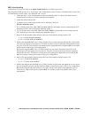
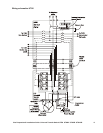
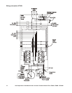
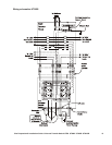
240 V circuit wiring
Consult the UTS Wiring Plan table in the Quick Install Guide that was filled in previously.
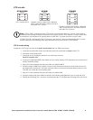
The UTS6 and UTS6H provide 120 V circuits only. The UTS6BI utilizes circuits 5 and 6 as a dedicated 240 V circuit. The
UTS10BI utilizes circuits 9 and 10 as a dedicated 240 V circuit.
1. Locate the 240 V, 2-pole circuit breakers on the circuit breaker panel. A 2-pole circuit breaker has an
interlock that forces the two circuits to open and close together.
2. Switch the circuit breakers OFF.
3. Loosen the screws securing the electrical wires, and remove the wires.
DO NOT trim these wires.
4. For a UTS6BI, locate wires 5 IN, 5 OUT and 6 IN, 6 OUT in the bundle of wires coming from the UTS.
Route these wires to the circuit breaker identified in Step 1.
5. For a UTS10BI, locate wires 9 IN, 9 OUT and 10 IN, 10 OUT in the bundle of wires coming from the
UTS. Route these wires to the circuit breaker identified in Step 1.
6. Strip off 5/8 inch insulation from the ends of the wires in the bundle coming from the UTS:
a. for a UTS6BI, 5 OUT and 6 OUT
b. for a UTS10BI, 9 OUT and 10 OUT
7. a) Insert the stripped 5 OUT wire (UTS6BI), and the wire previously disconnected from the circuit breaker
into a wire nut supplied in accessories kit. Twist the wire nut to ensure an electrical connection between the
two wires. Tuck the wires inside the circuit breaker panel. Repeat this process with the 6 OUT wire and the
second circuit breaker in the 2-pole configuration.
b) Insert the stripped 9 OUT wire (UTS10BI), and the wire previously disconnected from the circuit
breaker into a wire nut supplied in accessories kit. Twist the wire nut to ensure an electrical connection
between the two wires. Tuck the wires inside the circuit breaker panel. Repeat this process with the 10
OUT wire and the second circuit breaker in the 2-pole configuration.
8. Strip off 5/8 inch insulation from the ends of the wires in the bundle coming from the UTS:
a. for a UTS6BI, 5 IN and 6 IN
b. for a UTS10BI, 9 IN and
10 IN
9. a) Insert the stripped end of the 5 IN wire (UTS6BI), into the circuit breaker and tighten the screw to secure
the wire. Repeat this process with the 6 IN wire and the second circuit breaker in the 2-pole configuration.
b) Insert the stripped end of the 9 IN wire (UTS10BI), into the circuit breaker and tighten the screw to
secure the wire. Repeat this process with the 10 IN wire and the second circuit breaker in the 2-pole
configuration.