


Site Preparation & Installation Guide Universal Transfer Switch UTS6 UTS6H UTS6BI UTS10BI8
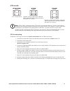
Surface mount installation
1. Hang the UTS on a nail using the mounting eyelet located on the rear of the unit.
2. Locate two 16 inch on center wall studs within one foot of the building circuit breaker panel.
3. Mark the wall identifying the location of the mounting tabs.
4. Secure the UTS to the wall using six screws appropriate for the UTS weight and the wall material on which
the unit is being installed.
5. Proceed to the section in this manual, Connect UTS to circuit breaker panel.
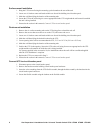
Flush mount installation
1. Remove the six surface mounting tabs on the UTS using pliers to break the tabs off.
2. Remove the screws that secure the cover on the UTS, and remove the cover.
3. Locate two 16 inch on center wall studs within one foot of the building circuit breaker panel.
4. Mark the wall identifying the desired location for the UTS.
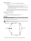
5. Cut an opening in the wall to accommodate the UTS, 21.3 in x 14.25 in (54.1 cm x 36.2 cm).
6. Mark the wall identifying the location of the mounting tabs.
7. Position the UTS in the opening. Secure the UTS to the wall using four screws appropriate for the UTS
weight and the wall material on which the unit is being installed.
Use spacers supplied in the accessories kit, for installations where the wall will have wallboard applied
after the UTS installation is complete.
8. Replace the UTS cover removed in Step 2.
9. Proceed to the section in this manual, Connect UTS to circuit breaker panel.
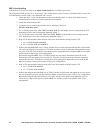
Connect UTS to circuit breaker panel
1. Disconnect power to the circuit breaker panel.
2. Remove the knockout on the building circuit breaker panel enclosure.
3. Insert the wires extending from the UTS flexible conduit, through the hole created by the knockout in the
circuit breaker panel enclosure.
4. Secure the flexible conduit using the locknut on the flexible conduit.