


Site Preparation & Installation Guide Universal Transfer Switch UTS6 UTS6H UTS6BI UTS10BI6
Site Planning and Preparation
Select a location
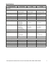
Select a suitable location that meets the environmental specifications and safety requirements of the UTS. Refer to the
Specifications table in this manual.
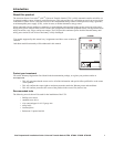
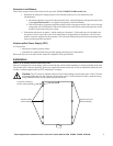
This unit is intended for wall mounting, either recessed into the wall for a flush mounting, or surface mounted on the wall.
The unit has built in brackets for mounting. Refer to the UTS Installation section in this manual for details.
The UTS must be installed within one foot of the building circuit breaker panel.
Determine circuit usage
The circuits in the circuit breaker panel should be labeled indicating the load each circuit supports. If the circuits are not
labeled, APC recommends working with a licensed electrician to label them.
With the assistance of a licensed electrician:
• determine which circuits support the most vital loads in the home, and should be connected to the UTS.
• determine which lights, appliances, and electrical devices are most essential and should have a backup power
supply in the event of a power outage.
• discuss what backup power sources are to be connected to the UTS.
• discuss the capabilities of the backup power sources to be connected to the UTS.
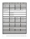
A Quick Install Guide is supplied with the UTS. In this guide find:
• the UTS Wiring Plan table that should be filled in with the electrician. This table will provide an overview of
circuits, connected loads, and voltage requirements for use when configuring the UTS.
• the Backup Power Sources Configuration table that should be filled in with the electrician. This table will
provide an overview of the backup power sources to be connected, and basic information concerning the
power source and configuration of the supporting circuits.
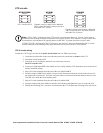
Note: Special note regarding Circuit1.
• Circuit1 loads will receive backup power ONLY from the BACKUP1 (GENERATOR) power source.
• The Convenience Outlet is powered by Circuit1.
The wattage of any load connected to the Convenience Outlet on the UTS is added to the wattage of any load
conneceted to Circuit1.
Backup power sources
Refer to the Specifications table in this manual for information on UTS circuit specifications.
Generators
Review the specifications and other important information for the generator to be connected to the UTS. This information
will determine the configuration of the UTS circuits.
Refer to the Specifications table in this manual for compatible generator specifications.