


15 Site Preparation & Installation Guide Universal Transfer Switch UTS6 UTS6H UTS6BI UTS10BI
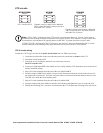
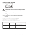
UTS Controls and Indicators
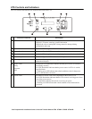
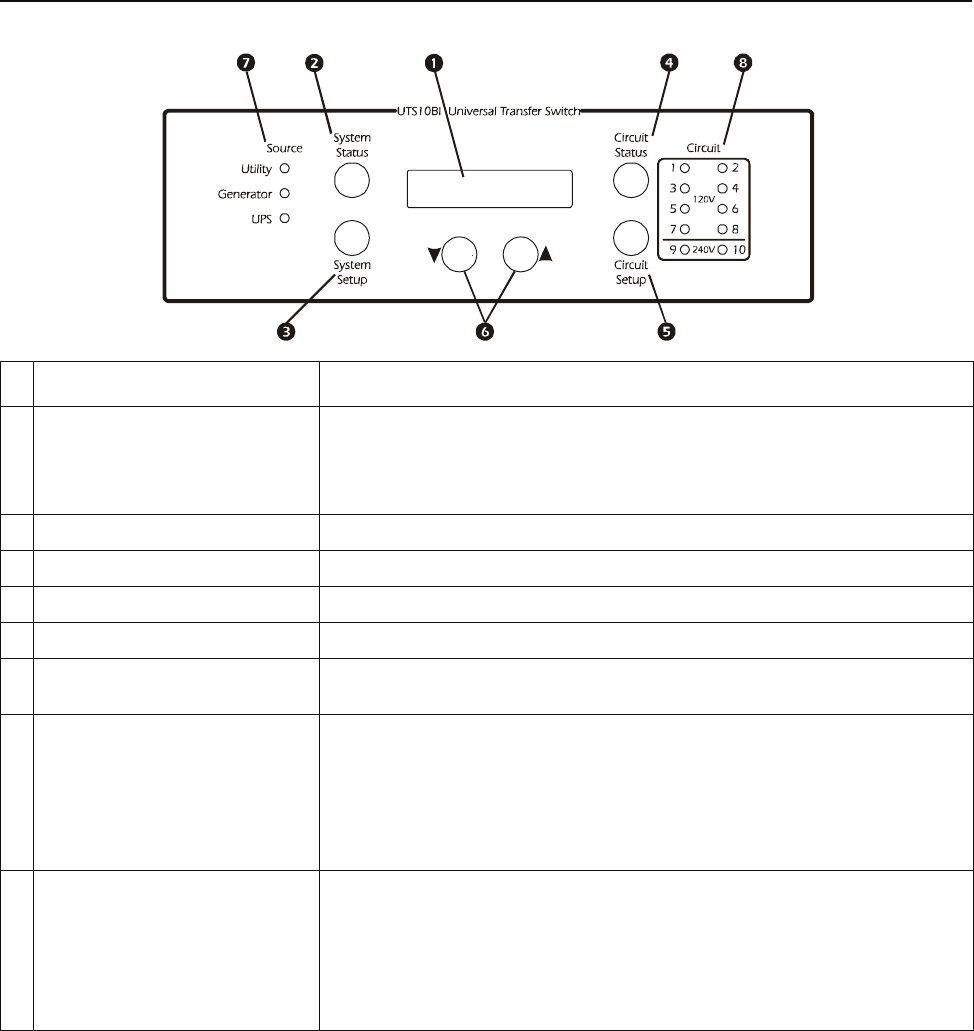
The UTS controls and indicators are located on the front of the UTS.
Control or Indicator Description
! LCD • Displays two lines with 20 characters per line
• Displays UTS status, warnings, general information
• Displays the value or setting that is being entered or changed during
configuration and setup
" System Status button Cycles the UTS through the default or selected system status options
# System Setup button Used to configure the UTS system options
$ Circuit Status button Cycles the UTS through the circuits displaying the status of each on the LCD
% Circuit Setup button Used to configure the UTS individual circuit options
& Down/Up arrow buttons Used to scroll through steps for configuration and to scroll between status and
informational displays
' Source LEDs
Utility
Generator
UPS
• Solid green LED illumination indicates that the power source is ON and is
functioning normally
• No LED illumination indicates that the power source is OFF or is outside
specified limits
• A flashing green LED indicates that a fault condition exists for that power
source, and should be corrected
( Circuit LEDs The number of circuit LEDs varies dependent on the model of UTS
• Red LED illumination indicates that the UTS circuit is receiving power from
one of the power sources
• No illumination indicates that circuit is receiving no power
• A flashing red LED indicates that a fault condition exists and should be
corrected