


User Manual version 2207
APOLLO 120/150 III
5-
58
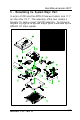
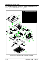
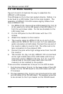
5.5. Touch Controller Assembly
If a touch screen is integrated with the system, the
touchscreen controller is to be installed right after the
installation of the motherboard.
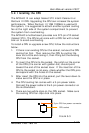
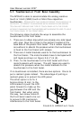
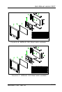
For easy maintenance in the future, the controller is to
installed to a bracket rather than to the system compartment
directly. From your point of view, there is a rectangle opening
at the left upper side of the chassis. Insert the touch
controller bracket to the opening and retain it to the chassis
with 2 flat-head 3*5 screws.
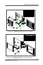
For easy assembly, the related cables are to be connected
first.
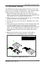
1. The touchscreen cable Fig. 5-1. (14) is a 10 pin to 10 pin
flat cable. One end is connected to the touchscreen
controller first.
2. There is a 2 pin (black & red) cable to provide the power
source for the touchscreen. Connect one end to the
controller.
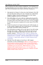
3. Connect the other end of the 10-pin to 10 pin flat cable to
the onboard COM 3 header connector and connect the
other end of the 2 pin power cable to the motherboard’s
PWR1.
4. Fix the touchscreen controller (13) to the bracket with 2
3*6 screws.
5. Fold both cables properly.
6. Make sure the two screws at the outward upper side of the
chassis are also properly fixed.