


User Manual version 2207
APOLLO 120/150 III
5-
64
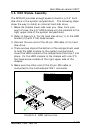
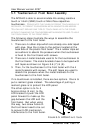
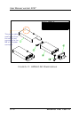
After finishing the LCD module installation, the module is to
be assembled to the front bezel module, then to the chassis
with the motherboard and touch controller already on.
1. Use special air blower to blow any dust between the LCD
and touchscreen before the two modules are assembled
together. Retain the LCD module and the front bezel
module together with six 3*6 screws.
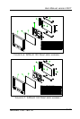
2. The LCD cable is 41-pin to 50-pin cable with around 30
cm in its length. Insert the 41-pin end into the opening at
the back side of the LCD holder and have it firmly plugged
to the LCD connector located at the rear side of the LCD
panel.
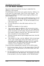
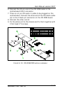
3. Install the whole front bezel module with LCD already on
to the system chassis with the motherboard, touchscreen
controller and HDD module already on.
4. The LCD cable is already at the rear side of the LCD holder
through the cutout. Make sure the 50 pin end is to go
through the rectangle opening at the rear side of the
system chassis. PLEASE NOTE THAT THERE IS A BROWN WIRE
SWINGING OUTSIDE OF THE 50 PIN END. THIS BROWN WIRE IS ONLY
TO BE WITH 12.1” SYSTEM. TAPE THE BROWN WIRE TO THE CABLE
TO PREVENT IT FROM SWING AROUND TO CAUSE POSSIBLE SHORT
CIRCUIRTRY.
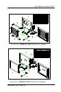
5. Connect the LCD cable to the 50 pin LCD header
connector on the motherboard. SPECIAL ATTENTION NEEDS TO
BE PAID WHEN PLUGGING THE LCD CABLE TO THE LCD HEADER
CONNECTOR ON THE MOTHERBOARD. ON THE 50 PIN END, PIN #1
IS MARKED WITH A WHITE POINT. MAKE SURE PIN 1 OF THE
ONBOARD LCD CONNECTOR MATCH PIN 1 OF THE CABLE ANY
WRONG PLUGGING OR SHIFTED PLUGGING WILL DAMAGE THE LCD
PANEL OR LEAD TO MAL-FUNCTION.