


Take Apart Logic Board - 37
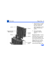
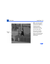
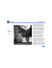
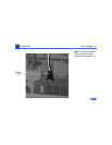
holes in the back of the
chassis. Lower the front of
the logic board so that the
pegs in the housing base fit
into the logic board holes.
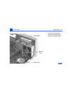
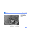
Press the front edge of the
logic board down until the
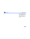
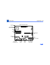
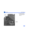
release tab clicks. Connect
all cables to the proper
sockets on the logic board.
(See the diagram on the
next page. Two 4-pin
connectors from the power
supply have no sockets, and
will remain unconnected.)
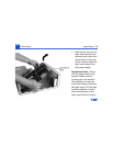
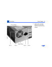
The LED connector must be
plugged in so that the arrow
goes over pin 1 on the logic