


64
Interface Specifications
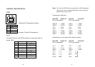
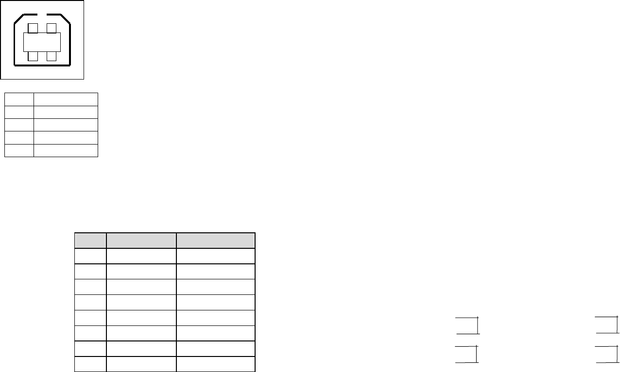
USB
Pin Signal Name
1 VBUS
2 D -
3 D+
4 GND
Serial
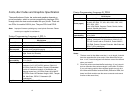
For the OS-214 plus, the RS232 connector on the printer side is a
female, DB-9.
Pin Direction Definition
1 In DSR
2 In RxData
3 Out TxData
5 - Ground
6 Out DTR
7 Out RTS
8 In CTS
9 Out +5V
12
3 4
12
3 4
USB series “B” Receptacle Interface
Connector Terminal Pin Assignment
65
Note: Pin 9 on the OS-214 plus is reserved for a KDU (keyboard
device unit). Do not connect these pins if you are using a
general host such as a PC.
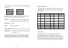
Connection with host:
Host 25S Printer 9P Host 9S Printer 9P
(PC or compatible) (PC or compatible)
DTR 20 …… 1 DSR DTR 4 …… 1 DSR
DSR 6 …… 6 DTR DSR 6 …… 6 DTR
TX 2 …… 2 RX TX 3 …… 2 RX
RX 3 …… 3 TX RX 2 …… 3 TX
CTS 5 …… 7 RTS CTS 8 …… 7 RTS
RTS 4 …… 8 CTR RTS 7 …… 8 CTS
GND 7 …… 5 GND GND 5 …… 5 GND
Alternatively you can connect the 3 wires as follows:
Host 25S Printer 9P Host 9S Printer 9P
(PC or compatible) (PC or compatible)
TX 2 …… 2 RX TX 3 …… 2 RX
RX 3 …… 3 TX RX 2 …… 3 TX
GND 7 …… 5 GND GND 5 …… 5 GND
pin 4 pin 4
pin 5 pin 6
pin 6 pin 7
pin 20 pin 8