


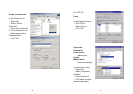
72
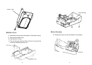
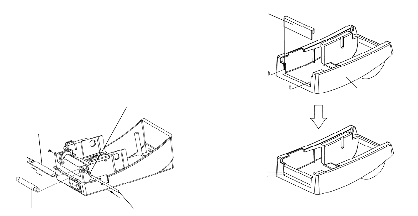
13. Unlatch the print head module. Hook the white roller on
the brackets of the chassis, ensuring the long thinner end
is on the left side.
14. Guide the shaft through the respective holes on the left
bracket, the white roller and then the right bracket in order.
(To smooth this procedure, hold the white roller with one
hand.)
15. Secure the attached screw to the right bracket of the
chassis to fix the shaft.
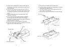
16. Hook the dispenser bar on the brackets of the chassis,
positioning it above the white roller. Ensure that the
dispenser bar is parallel with the black platen roller and its
long thinner end is on the left.
17. Secure the screw on the left bracket of the chassis.
18. Guide the sensor cable connector through the hole on the
upper left corner of the middle cover.
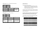
Screw
Shaft
White Plastic Roller
Dispenser Bar
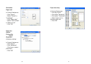
73
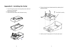
19. Click the top cover back onto the middle cover.
20. Insert the sensor connector into its receptacle on the main
logic board of the base housing.
21. Click the middle cover back into the base housing. First
click in the front then the rear.
22. Secure the two screws at the bottom of the base housing.
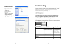
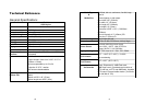
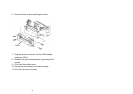
H. Cover
Middle Cover
4 mm Gap