


4
CONTROLS AND OPERATION
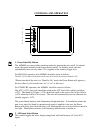
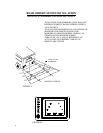
1. Power/Stand-By Button
The AOM681 has two possible operation modes for turning the unit on/off. In manual
mode, the power button is used to turn the unit on/off. In stand-by mode, the unit
automatically turns on only when 12V is applied to the stand-by trigger wire.
For MANUAL operation, the AOM681 should be wired as follows:
The ACC (+12V) lead (red) should be wired to the ACC feed of the vehicle (switched +12V).
*Please note that if the unit is in “Stand-by On” mode, the Power Button will appear to
have no effect (it will switch from “on” to “on” in this case).
For STAND-BY operation, the AOM681 should be wired as follows:
The ACC (+12V) lead (red) should be wired to the ACC feed of the vehicle (switched
+12V). The Stand-by Trigger (+12V) should be wired to the reverse feed of the vehicle
(+12V when the vehicle is in reverse). The unit will automatically turn on whenever the
standby trigger is +12V.
The power button features dual-illumination (bright and dim). In installations where the
unit is not wired for Stand-by operation and power is applied to the unit, the Power
Button will dimly glow when the unit is off, allowing the user to easily find the control in
low light. Illumination switches to full intensity when the unit is turned on.
2. A/B Input Select Button
This control toggles the active display image back and forth between AV1 and AV2
inputs.
1
2
3
4
5
5