


6
INSTALLATION INSTRUCTIONS
BEFORE YOU BEGIN INSTALLATION:
Before drilling, be sure that no cable or wiring is on the other side. Clamp all wires
securely to reduce the possibility of them being damaged during installation and use.
Keep all cables away from hot or moving parts, and electrically noisy components.
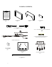
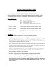
Wiring Definitions:
? Power connection: Pin 1 ACC +12V (Red)
Pin 2 Standby Trigger (Blue wire)
Pin 3 Ground (Black wire)
Pin 4 Audio Trigger (Blue w/white stripe wire)
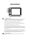
? Camera A input: Connection for camera or camera extension cable
? Camera B input: Connection for camera or camera extension cable
? LCD panel: 9-pin DIN cable connection: junction box to monitor.
Procedure:
1. Choose the monitor, junction box, and camera mounting locations.
2. Install all required cables in vehicle. A ¾” (19mm) hole should be drilled for passing
cables through vehicle walls, barriers, etc. After the intermediate cable is passed
through the hole, install the split grommet (included). If additional cable protection is
required install convoluted tubing over the cable.
3. After cable/wiring has been routed and components are in place, temporarily make all
system connections and perform a system function check. If system does not operate
properly, see the troubleshooting section of this manual.
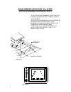
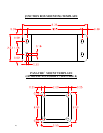
4. If using an optional PanaVise
?
stalk mount (available separately), use the mounting
template provided on page 10. Install the PanaVise
?
mount to the LCD monitor
using the #10 self-drilling screws (included).
**Important: Do not use screws other than those provided with the AOM681.
Void of warranty and serious product damage will occur.
5. Use the template provided on page 10 for proper placement of the junction box
mounting holes. Use the #8 self-drilling screws (included) to secure the junction box
in the desired location. The junction box can also be mounted using the 2”x 4” velcro
strip (included).