20 ASUS P4T-EM User’s Manual
3. HARDWARE SETUP
Motherboard Settings
3. H/W SETUP
®
P4T-EM
P4T-EM CNR/USB Selection
CNRUSB
USB2
(Default)
OC3
1
2
J3-
J3+
2
3
OC3
J3-
J3+
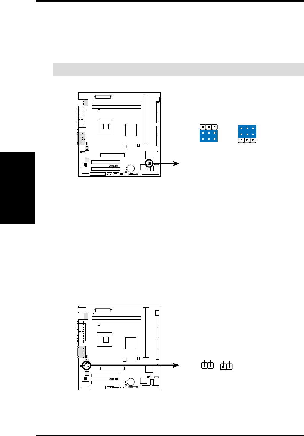
6) USB2 / CNRUSB Selection (J3-J3+, OC3)
The CNR slot can support an optional USB hub CNR card. Three jumpers are
used to control selection of USB or CNR functions: J3-, J3+ and OC3. The
factory default setting is for standard USB2 control. If a USB hub CNR card is
used, reset these jumpers to CNRUSB setting shown below.
IMPORTANT! Always set all three jumpers accordingly when selecting a device.
®
P4T-EM
P4T-EM Internal Line Out Connectors
J11 J12
LAP_LT
LAP_LTT
LAP_RT
LAP_RTT
7) Intel Front Panel Audio Selection (J11, J12)
The motherboard ships with two jumper caps on both J11 and J12, adjacent to
the INTEL_FPANEL1 connector. The caps-on default completes the circuit for
use of regular audio external connectors, ie.: Line_out. If using the
INTEL_FPANEL1 cable and/or front panel, then remove J11 and J12 jumper
caps. Do not remove the jumper caps unless the INTEL_FPANEL1 cable
connector is used. (See page 39 for the INTEL_FPANEL1 connector.)


