


ASUS P4T-EM User’s Manual 35
3. HARDWARE SETUP
Connectors
3. H/W SETUP
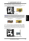
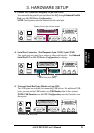
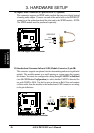
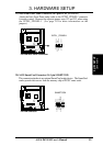
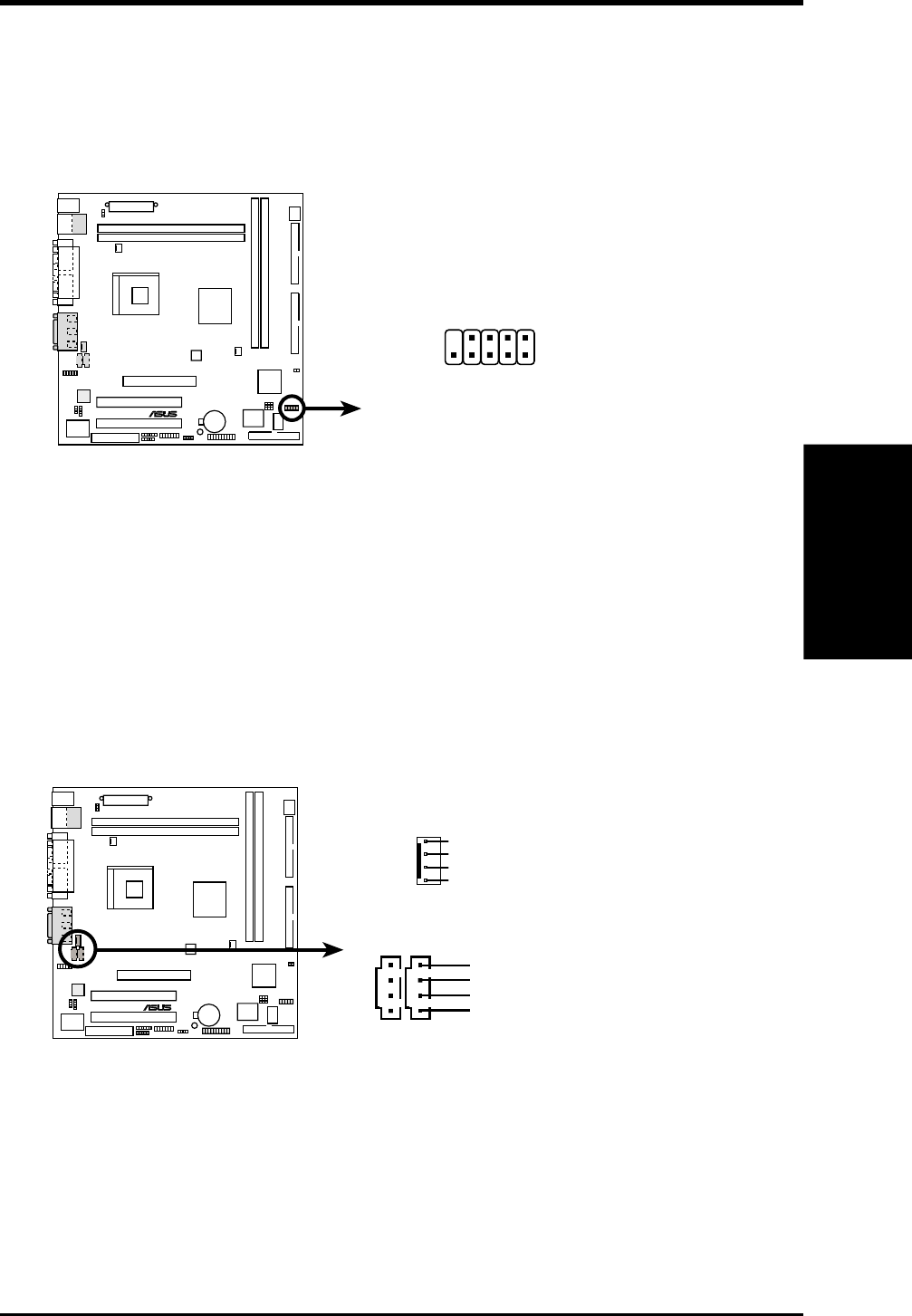
12) USB Headers (10-1 pin USB2)
If the USB Ports on the back panels are inadequate, a USB header is available
for two additional USB ports. Connect the 10-1 pin ribbon cable from the pro-
vided 2-port USB connector set to the midboard 10-1 pin USB header and mount
the USB connector set to an open slot on your chassis.
®
P4T-EM
P4T-EM USB Headers
USB2
15
610
1: USB Power
2: USBP2–
3: USBP2+
4: GND
5: NC
6: USB Power
7: USBP3–
8: USBP3+
9: GND
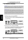
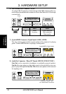
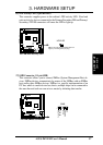
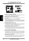
13) Internal Audio Connectors (4-pin MODEM, CD_IN, AUX)
These connectors allow you to receive stereo audio input from such audio-vi-
sual sources as a CD-ROM input, or MPEG card.
®
P4T-EM
P4T-EM Internal Audio Connectors
MODEM
Modem-Out
Ground
Modem-In
Ground
Right Audio Channel
Left Audio Channel
Ground
Ground
CD1 (Black)
AUX (White)