


1-201-20
1-201-20
1-20
Chapter 1: Hardware informationChapter 1: Hardware information
Chapter 1: Hardware informationChapter 1: Hardware information
Chapter 1: Hardware information
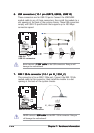
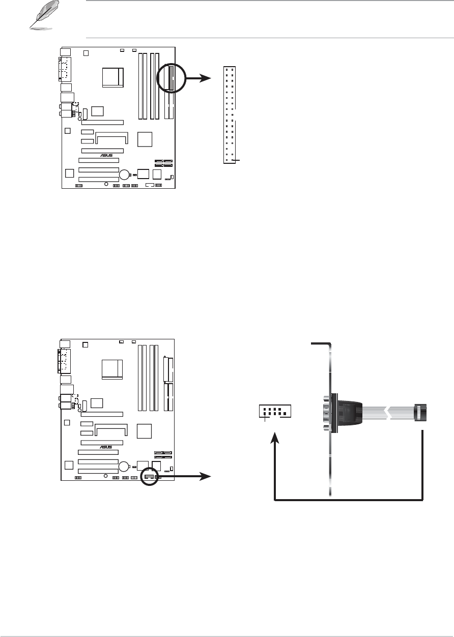
The Pin 5 on the connector is removed to prevent incorrect cable
connection when using an FDD cable with a covered Pin 5.
1.7.21.7.2
1.7.21.7.2
1.7.2
Internal connectorsInternal connectors
Internal connectorsInternal connectors
Internal connectors
1.1.
1.1.
1.
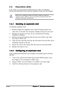
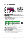
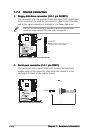
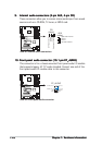
Floppy disk drive connector (34-1 pin FLOPPY)Floppy disk drive connector (34-1 pin FLOPPY)
Floppy disk drive connector (34-1 pin FLOPPY)Floppy disk drive connector (34-1 pin FLOPPY)
Floppy disk drive connector (34-1 pin FLOPPY)
This connector is for the provided floppy disk drive (FDD) signal cable.
Insert one end of the cable to this connector, then connect the other
end to the signal connector at the back of the floppy disk drive.
A8N-SLI
®
A8N-SLI Floppy disk drive connector
NOTE: Orient the red markings on
the floppy ribbon cable to PIN 1.
PIN 1
FLOPPY
2.2.
2.2.
2.
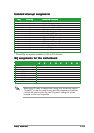
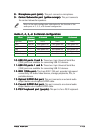
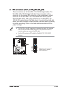
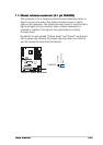
Serial port connector (10-1 pin COM1)Serial port connector (10-1 pin COM1)
Serial port connector (10-1 pin COM1)Serial port connector (10-1 pin COM1)
Serial port connector (10-1 pin COM1)
This connector is for a serial (COM) port. Connect the serial port
module cable to this connector, then install the module to a slot
opening at the back of the system chassis.
A8N-SLI
®
A8N-SLI COM port connector
PIN 1
COM1