


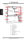
22
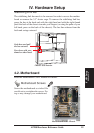
IV. Hardware Setup
AP200 Hardware Reference Guide
IV. HW Setup
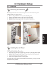
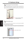
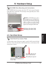
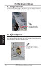
Floppy Disk Drive Cable Connections
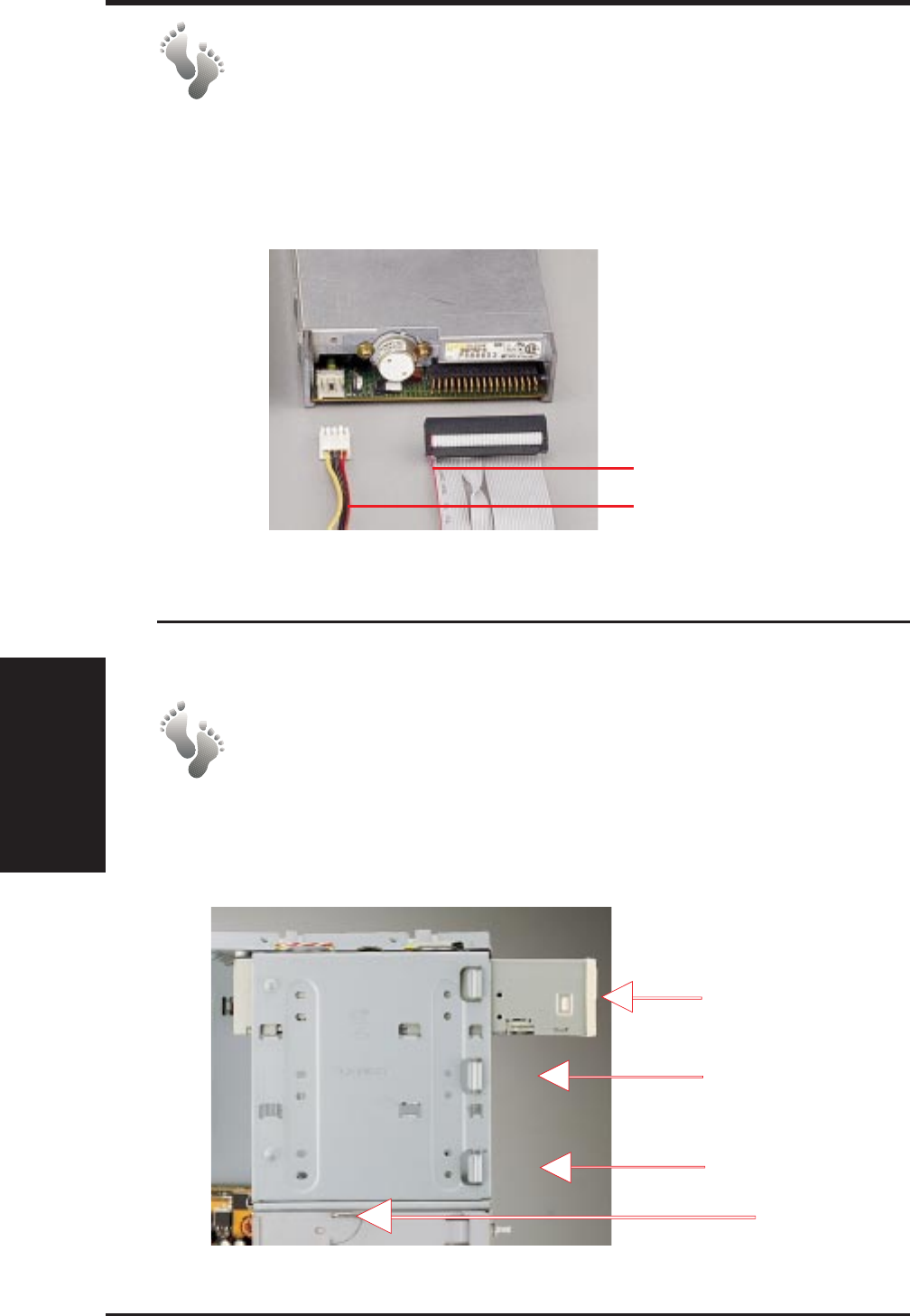
The 1.44MB floppy disk drive requires signal and power connections. Align
the red stripes of the signal and power cables so that they face each other.
Carefully insert the connector while visually watching the progress so that
proper alignment and insertion is made.
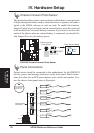
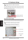
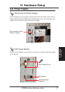
5.25” Device Cage
4-4. 5.25” Device Cage
Before CD-ROM, tape, or hard disk drives can be installed or removed from
the 5.25” device cage, you must remove the device cage from the chassis.
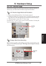
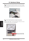
5.25” Device Cage Removal Procedure
1. Rotate the locking lever. (See 4-4. 3.25” Device Cage.)
2. Pull the device cage to the left side of the chassis.
To mount the 5.25” device cage, use the reverse procedure.
Red stripe of signal cable
Red stripe of power cable
1.44MB Floppy Disk Drive Connections
5.25” Device Bay 3
5.25” Device Bay 2
5.25” Device Bay 1
5.25” Device Cage with a CD-ROM in its
Topmost Bay
Locking
Lever