


ASUS K8V-F motherboard user guide
1-23
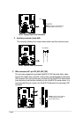
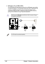
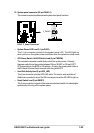
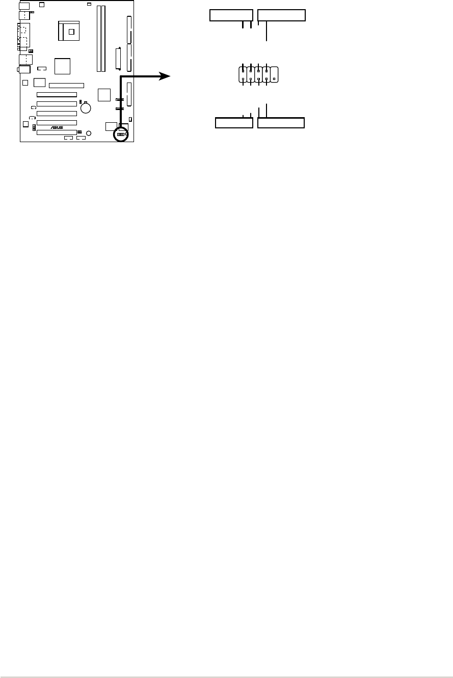
10. System panel connector (20-pin PANEL1)
This connector accommodates several system front panel functions.
• System Power LED Lead (3-1 pin PLED)
This 3-1 pin connector connects to the system power LED. The LED lights up
when you turn on the system power, and blinks when the system is in sleep mode.
• ATX Power Switch / Soft-Off Switch Lead (2-pin PWRSW)
This connector connects a switch that controls the system power. Pressing
thepower switch turns the system between ON and SLEEP, or ON and SOFT
OFF,depending on the BIOS or OS settings. Pressing the power switch while in
theON mode for more than 4 seconds turns the system OFF.
• Hard Disk Activity Lead (2- pin IDE_LED)
This 2-pin connector is for the HDD LED cable. The read or write activities of
thedevice connected to any of the IDE connectors cause the IDE LED to light up.
• Reset Switch Lead (2-pin RESET)
This 2-pin connector connects to the case-mounted reset switch for rebootingthe
system without turning off the system power.
K8V-F
®
K8V-F F_Panel Connector
F_PANEL
IDE LED-
Power LED+
IDE LED+
Ground
Power LED-
Power Switch
Ground
Reset
IDE_LED
Reset Switch
Power LED Power Switch