


ASUS M2NBP-VM CSM 1-29
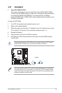
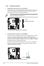
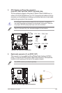
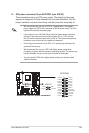
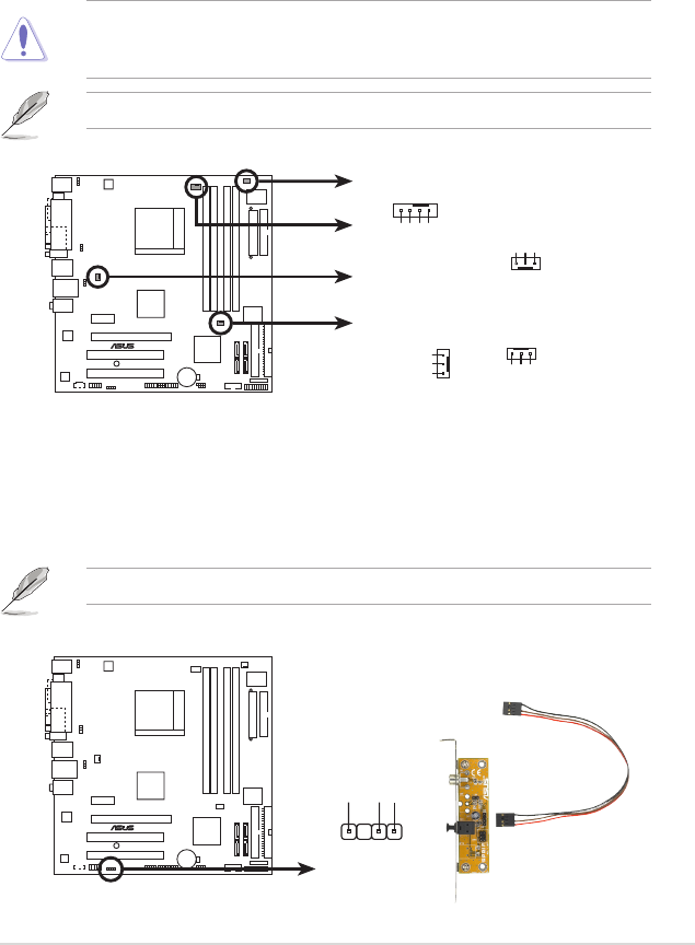
5. CPU, Chassis, and Power Fan connectors
(4-pin CPU_FAN, 3-pin CHA_FAN1/2, 3-pin PWR_FAN)
The fan connectors support cooling fans of 350mA~740mA (8.88W max.) or
a total of 1A~2.22A (26.64W max.) at +12V. Connect the fan cables to the fan
connectors on the motherboard, making sure that the black wire of each cable
matches the ground pin of the connector.
Do not forget to connect the fan cables to the fan connectors. Insufcient air
ow inside the system may damage the motherboard components. These are
not jumpers! DO NOT place jumper caps on the fan connectors.
M2NBP-VM CSM
®
M2NBP-VM CSM Fan connectors
CHA_FAN1
CPU_FAN
GND
Rotation
+12V
CHA_FAN1
GND
CPU FAN PWR
CPU FAN IN
CPU FAN PWM
CPU_FAN
CHA_FAN2
GND
Rotation
+12V
PWR_FAN
GND
Rotation
+12V
CHA_FAN2
PWR_FAN
M2NBP-VM CSM
®
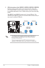
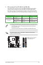
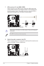
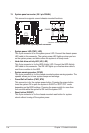
M2NBP-VM CSM Digital audio connector
+5V
SPDIFOUT
GND
SPDIF_OUT
6. Digital audio connector (4-1 pin SPDIF_OUT)
This connector is for an additional Sony/Philips Digital Interface (S/PDIF)
port(s). Connect the S/PDIF module cable to this connector, then install the
module to a slot opening at the back of the system chassis.
The S/PDIF module is purchased separately.
Only CPU Fan and CHA_Fan1 connectors support Q-Fan2 function.