


1-8
Chapter 1: Product introduction
Chapter 1
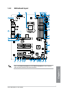
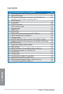
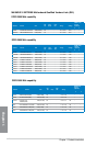
Layout contents
Connectors/Jumpers/Buttons and switches/Slots Page
1. Power connectors (24-pin EATXPWR, 8-pin EATX12V, 4-pin EATX12V) 1-43
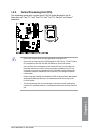
2. LGA1150 CPU Socket
1-9
3. CPU, chassis, and optional fan connectors (4-pin CPU_FAN, 4-pin
CPU_OPT, 4-pin OPT_FAN1-3, 4-pin CHA_FAN1-3)
1-41
4. DDR3 DIMM slots
1-10
5. Q_Code LEDs
1-30
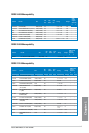
6. PCIe x16 Lane switch
1-25
7. START (Power-on) button
1-22
8. Slow Mode switch
1-24
9. RESET button
1-22
10. MemOK! button
1-23
11. Thermal sensor cable connectors (2-pin OPT_TEMP1-3)
1-45
12. USB 3.0 connectors (20-1 pin USB3_12)
1-38
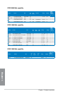
13. LN2 Mode header
1-27
14. Intel® Z87 Serial ATA 6.0 Gb/s connectors (7-pin SATA6G_1-6 [red])
1-37
15. ASMedia® Serial ATA 6.0 Gb/s connectors (7-pin SATA6G_E12/E34 [red])
1-38
16. BIOS Switch button
1-24
17. System panel connector (20-8 pin PANEL)
1-44
18. DRCT connector
1-46
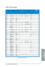
19. USB 2.0 connectors (10-1 pin USB910; USB1112; USB1314)
1-40
20. ROG Extension connector (18-1 pin ROG_EXT)
1-47
21. DirectKey button
1-26
22. Fast Boot switch
1-25
23. Front panel audio connector (10-1 pin AAFP)
1-42
24. Digital audio connector (4-1 pin SPDIF_OUT)
1-39
25. EZ Plug connectors (6-pin EZ_PLUG_1; 4-pin EZ_PLUG_2)
1-45
26. mPCIe Combo II slot (MPCIE_COMBO_II)
1-46