


16 ASUS ME-99B User’s Manual
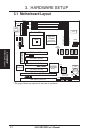
3. HARDWARE SETUP
Motherboard Settings
3. H/W SETUP
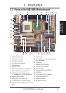
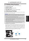
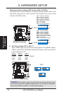
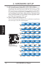
Motherboard Feature Settings (DIP Switches–DSW1 & DSW2)
The motherboard’s onboard functions are adjusted through the DIP switches. The
white block represents the switch’s position. The example below shows all the
switches in the OFF position.
DSW2
ON
12345678
OFF
ON
DSW1
ON
12345678
ON
OFF
ME-99B DIP Switches
01
®
ME-99B
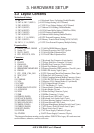
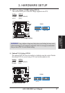
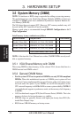
SW1-1 Frequency Selection
SW1-2 Frequency Selection
SW1-3 Frequency Selection
SW1-4 Frequency Selection
SW1-5
Memory Data Transfer
SW1-6
VIO Setting
SW1-7
VIO Setting
SW1-8
Core Voltage Setting
SW2-1 Frequency Multiple
SW2-2 Frequency Multiple
SW2-3 Frequency Multiple
SW2-4 Frequency Multiple
SW2-5
Onboard VGA Setting
SW2-6
Display Memory Setting
SW2-7 LCD Setting
SW2-8
Onboard Audio Setting
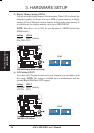
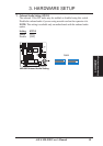
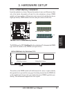
2) I/O Voltage Setting (SW1-6, SW1-7)
These switches allow you to select the voltage supplied to the DRAM, chipset,
AGPset, and the CPU’s I/O buffer. Setting both switches to [ON] increases the
voltage supplied by 0.3V.
Setting SW1-6 SW1-7
Normal [OFF] [OFF] (default)
+0.2V [ON] [OFF]
+0.3V [ON] [ON]
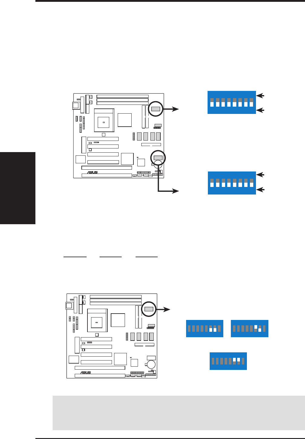
ME-99B I/O Voltage Setting
01
®
ME-99B
DSW1
ON
12345678
ON
12345678
Normal
(Default)
Add 0.2 Volt
ON
12345678
Add 0.3 Volt
WARNING! Using higher voltages may help when overclocking but may result
in the shortening of your computer component’s life. It is strongly recommended
that you leave SW1-6 and SW1-7 on their default settings.