


34 ASUS ME-99B User’s Manual
Connectors
3. H/W SETUP
3. HARDWARE SETUP
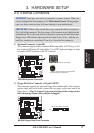
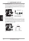
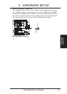
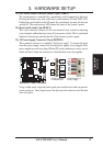
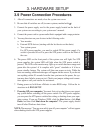
15) Audio Jack Header (25-1 pin AUDIOCON)
This header is provided for audio input and output signals. Using a ribbon cable,
you can connect this header to a back panel audio connecotr.
ME-99B Audio Jack Header
Line Output (1/8” phono)
Line Input (1/8” phono)
Microphone In (1/8” phono)
Game/MIDI Port (15 pins)
Audio Connector Module
12
Red stripe
2
1
26
25
01
®
ME-99B
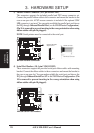
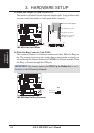
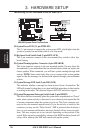
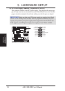
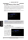
16) Wake-On-Ring Connector (2-pin WOR)
This connector connects to an internal modem card with a Wake-On-Ring out-
put. The connector powers up the system when a ringup packet or signal is re-
ceived through the internal modem card. NOTE: For external modems, Wake-
On-Ring is detected through the COM port.
IMPORTANT: This feature requires that PWR Up On Modem Act is set to
Enabled (see 4.5.1 Power Up Control).
ME-99B Wake-On-Ring Connector
WOR
01
®
ME-99B
Pin2 PIXRI#
Pin1 Ground