


ASUS ME-99B User’s Manual 27
3. HARDWARE SETUP
Connectors
3. H/W SETUP
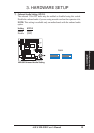
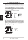
3.8 External Connectors
WARNING! Some pins are used for connectors or power sources. These are
clearly distinguished from jumpers in 3.1 Motherboard Layout. Placing jumper
caps over these connector pins will cause damage to your motherboard.
IMPORTANT: Ribbon cables should always be connected with the red stripe on
Pin 1 side of the connector. The four corners of the connectors are labeled on the
motherboard. Pin 1 is the side closest to the power connector for hard drives and
floppy drives. IDE ribbon cables must be less than 46 cm (18 in.), with the sec-
ond drive connector no more than 15 cm (6 in.) from the first connector.
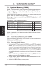
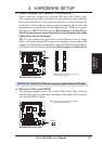
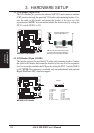
1) Keyboard Connector (5-pin KB)
This connector supports either a standard IBM-compatible, 101/102-key, or 104-
key keyboard (Windows 95-compatible). Use a PS/2 keyboard adapter in order
to connect a PS/2 keyboard to this AT connector.
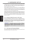
ME-99B Keyboard Connector
Keyboard Connector (5-pin female)
This motherboard accepts an AT Keyboard
Connector Plug as shown here.
01
®
ME-99B
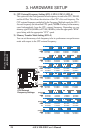
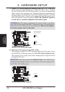
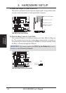
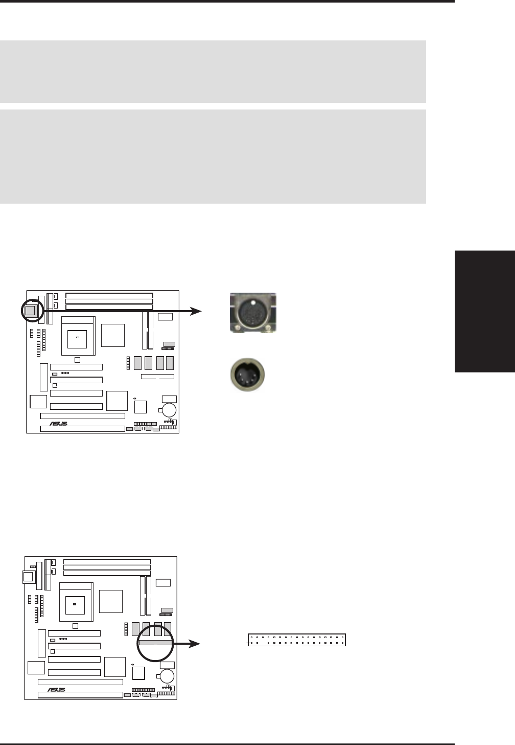
2) Floppy Disk Drive Connector (34-1pin FLOPPY)
This connector supports the provided floppy drive ribbon cable. After connect-
ing the single end to the board, connect the two plugs on the other end to the
floppy drives. (Pin 5 is removed to prevent inserting in the wrong orienta-
tion when using ribbon cables with pin 5 plugged).
01
®
ME-99B
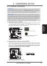
ME-99B Floppy Disk Drive Connector
Pin 1
Floppy Disk Drive Connector