


32 ASUS ME-99B User’s Manual
Connectors
3. H/W SETUP
3. HARDWARE SETUP
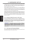
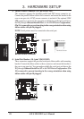
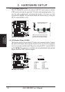
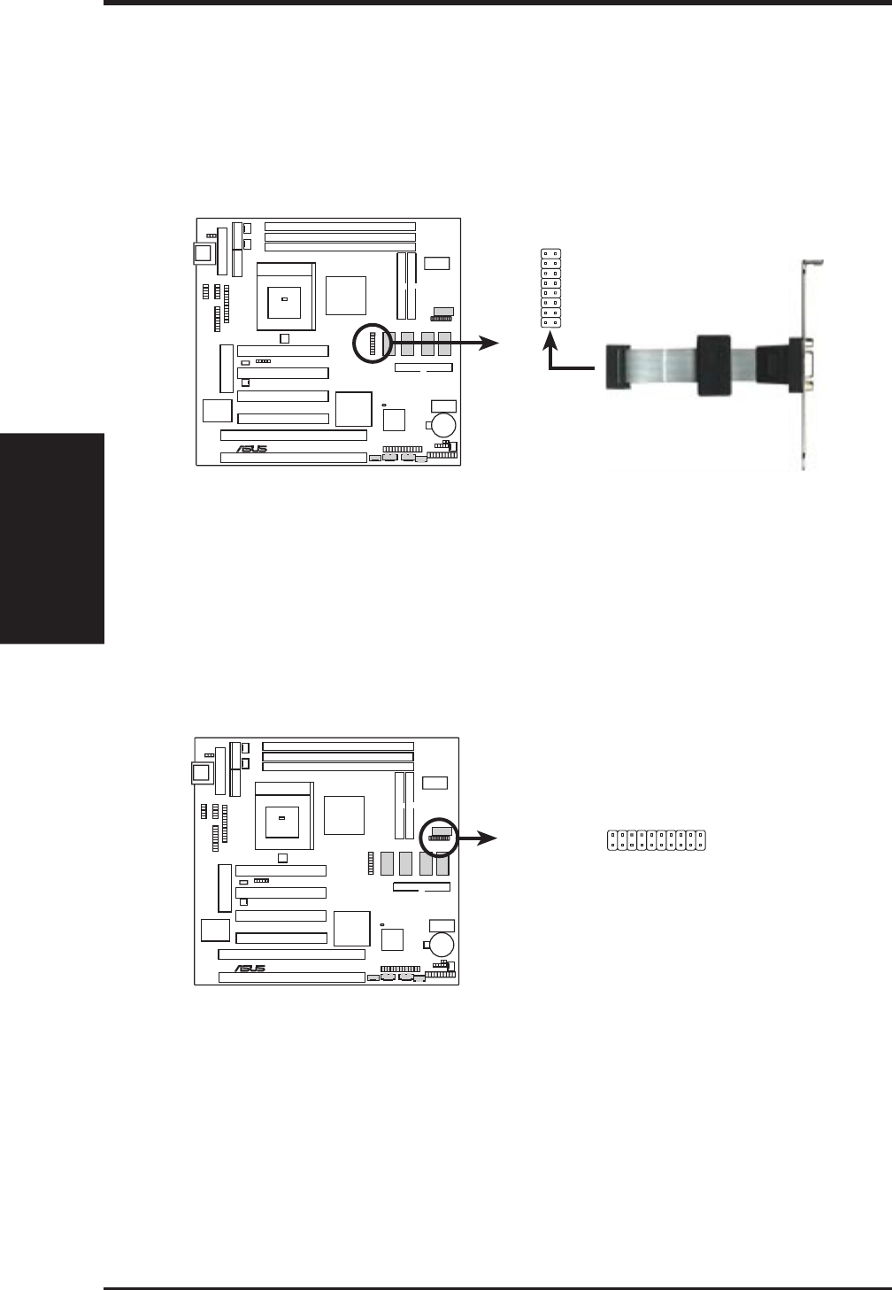
11) VGA Header (16-pin VGA)
The VGA Header lets you use the onboard AGP VGA and connect a standard
(CRT) monitor through the provided VGA cable with mounting bracket. Con-
nect the cable to this header and mount the bracket to the case on a free
expansionslot. NOTE: You can make available the monitor port by setting the
SW2-5 switch (DSW2) to ON.
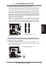
Bracket to end
approximately 6inch
Orient the red stripe on the
monitor cable with pin 1
TIP: You may also remove the bracket
connector and mount them directly to
the case to save expansion slot space.
ME-99B VGA Header
16
12
15
01
®
ME-99B
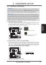
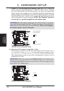
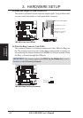
12) LCD Header (20-pin LCDHD)
This header supports the provided LCD cable with mounting bracket. Connect
the cable to this header and mount the bracket to the case on a free expansion
slot. You can make available the LCD port by setting the SW2-7 switch (DSW2)
to ON. NOTE: This connector is available only on motherboards with optional
Digital Flat Panel (DFP) interface support.
ME-99B LCD Header
01
®
ME-99B
LCDHD
1
11
10
20
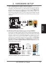
11: FDDCDAT
12: 0+5V
13: TXC-
14: GND
15: TX0+
16: TX1-
17: GND
18: TX2+
19: (No connection)
20: (No connection)
1: FDDCCLK
2: PLSENSE
3: GND
4: TXC+
5: TX0-
6: GND
7: TX1+
8: TX2-
9: GND
10: (No connection)