


2-26 Chapter 2: Hardware information
2.7.2 Internal connectors
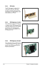
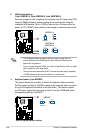
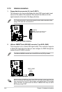
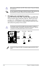
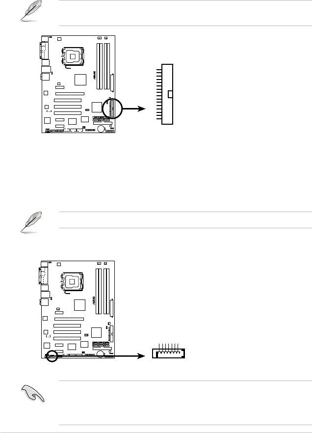
1. Floppy disk drive connector (34-1 pin FLOPPY)
This connector is for the provided oppy disk drive (FDD) signal cable. Insert
one end of the cable to this connector, then connect the other end to the
signal connector at the back of the oppy disk drive.
Pin 5 on the connector is removed to prevent incorrect cable connection when
using a FDD cable with a covered Pin 5.
P5B-E
®
P5B-E Floppy disk drive connector
NOTE: Orient the red markings on
the floppy ribbon cable to PIN 1.
FLOPPY
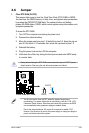
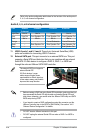
2. JMicron JMB363
®
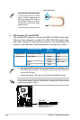
Serial ATA RAID connector (7-pin SATA_RAID)
This connector is for a Serial ATA signal cable. This connector supports
a Serial ATA hard disk drive that you can configure for RAID through the
onboard Serial ATA RAID controller.
The JMicron JMB363 controller item in the BIOS is set to [IDE] by default..
Before creating a RAID set using Serial ATA hard disks, make sure that you
have connected the Serial ATA signal cables and installed Serial ATA hard disk
drives; otherwise, you cannot enter the JMicron
®
JMB363 RAID utility and SATA
BIOS setup during POST.
P5B-E
®
P5B-E SATA_RAID connector
SATA_RAID
GND
RSATA_TXP1
RSATA_TXN1
GND
RSATA_RXP1
RSATA_RXN1
GND