


ASUS P5B-E 2-31
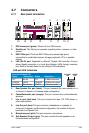
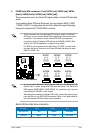
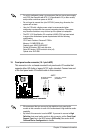
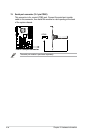
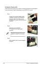
9. ATX power connectors (24-pin EATXPWR, 4-pin EATX12V)
These connectors are for ATX power supply plugs. The power supply plugs
are designed to t these connectors in only one orientation. Find the proper
orientation and push down rmly until the connectors completely t.
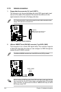
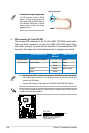
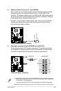
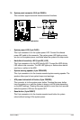
8. Chassis intrusion connector (4-1 pin CHASSIS)
This connector is for a chassis-mounted intrusion detection sensor or switch.
Connect one end of the chassis intrusion sensor or switch cable to this
connector. The chassis intrusion sensor or switch sends a high-level signal to
this connector when a chassis component is removed or replaced. The signal
is then generated as a chassis intrusion event.
By default , the pin labeled “Chassis Signal” and “ Ground” are shorted with
a jumper cap. Remove the jumper caps only when you intend to use the
chassis intrusion detection feature.
P5B-E
®
P5B-E Chassis intrusion connector
CHASSIS
+5VSB_MB
Chassis Signal
GND
(Default)
P5B-E
®
P5B-E ATX power connectors
EATXPWR
+3 Volts
+3 Volts
Ground
+5 Volts
+5 Volts
Ground
Ground
Power OK
+5V Standby
+12 Volts
-5 Volts
+5 Volts
+3 Volts
-12 Volts
Ground
Ground
Ground
PSON#
Ground
+5 Volts
+12 Volts
+3 Volts
+5 Volts
Ground
EATX12V
+12V DC
GND
+12V DC
GND
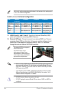
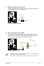
• Make sure to remove the cap on the EATX12V connector before connecting
an 4-pin EPS +12V power plug.
• Use only 4-pin ATX12V EPS +12V power plug for the EATX12V connector.