


2-28 Chapter 2: Hardware information
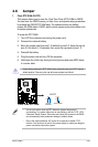
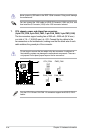
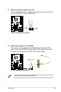
Connect the right-angle side
of SATA signal cable to SATA
device. Or you may connect the
right-angle side of SATA cable to
the onboard SATA port to avoid
mechanical conflict with huge
graphics cards.
right angle side
P5B-E
®
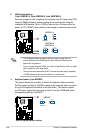
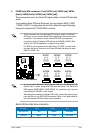
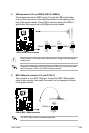
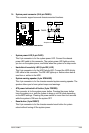
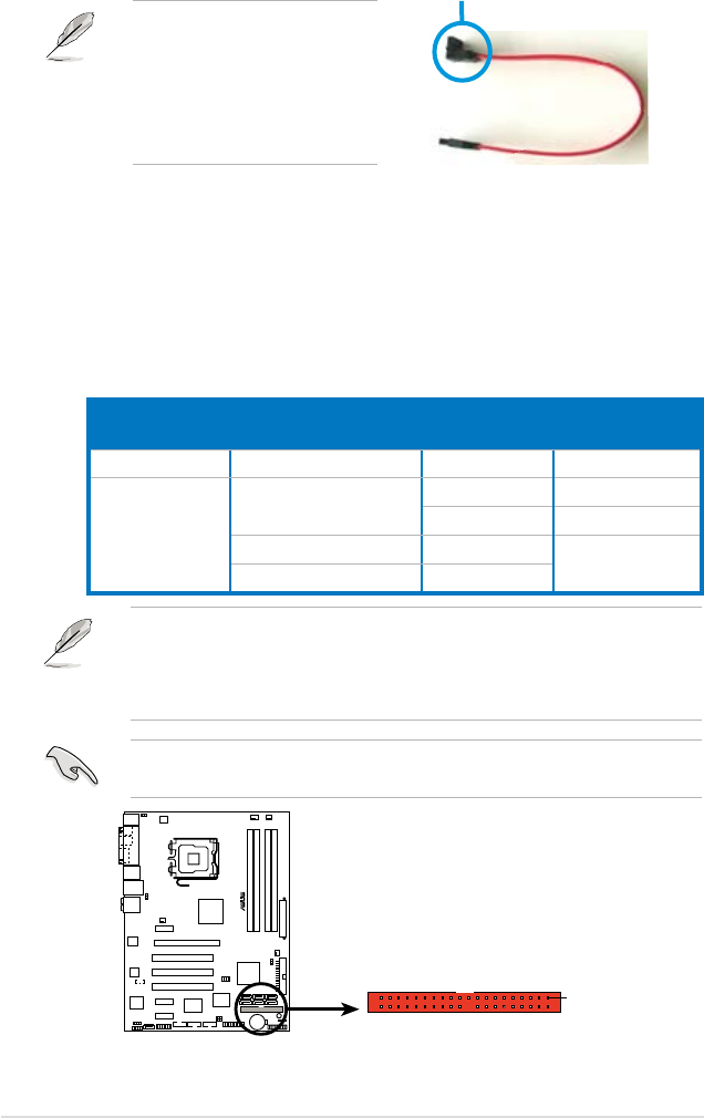
P5B-E IDE connector
NOTE: Orient the red markings
(usually zigzag) on the IDE
ribbon cable to PIN 1.
PRI_IDE
PIN 1
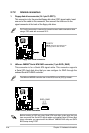
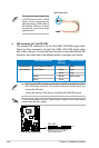
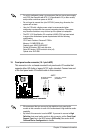
4. IDE connector (40-1 pin PRI_IDE)
The onboard IDE connector is for the Ultra DMA 133/100/66 signal cable.
There are three connectors on each Ultra DMA 133/100/66 signal cable:
blue, black, and gray. Connect the blue connector to the motherboard’s IDE
connector, then select one of the following modes to congure your device.
• Pin 20 on the IDE connector is removed to match the covered hole on the
Ultra DMA cable connector. This prevents incorrect insertion when you
connect the IDE cable.
• Use the 80-conductor IDE cable for Ultra DMA 133/100/66 IDE devices.
If any device jumper is set as “Cable-Select,” make sure all other device
jumpers have the same setting.
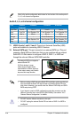
Drive jumper setting Mode of
device(s)
Cable connector
Single device Cable-Select or Master - Black
Two devices Cable-Select Master
Black
Slave Gray
Master Master Black or gray
Slave Slave