


1-4 Chapter 1: System introduction
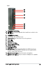
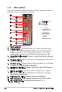
1.3 Rear panel
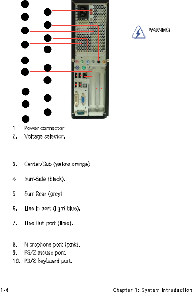
The system rear panel includes the power connector and several I/O ports
that allow convenient connection of devices.
1. Power connector
2. Voltage selector. This switch allows you to adjust the system input
voltage according to the voltage supply in your area. If the voltage
supply in your area is 100-127V, set this switch to 115V. If the
voltage supply in your area is 200-240V, set this switch to 230V.
3. Center/Sub (yellow orange). This port connects the center/subwoofer
speakers.
4. Surr-Side (black). This port connects the side speakers in an 8-channel
audio conguration.
5. Surr-Rear (grey). This port connects the rear speakers on a 4-channel,
6-channel, or 8-channel audio conguration.
6. Line In port (light blue). This port connects the tape, CD, DVD player,
or other audio sources.
7. Line Out port (lime). This port connects a headphone or a speaker.
In 4-channel and 6-channel conguration, the function of this port
becomes Front Speaker Out.
8. Microphone port (pink). This port connects a microphone.
9. PS/2 mouse port. This green 6-pin connector is for a PS/2 mouse.
10. PS/2 keyboard port. This purple 6-pin connector is for a
PS/2 keyboard.
1
2
4
5
6
3
10
11
12
7
8
9
14
13
15
16
17
WARNING!
Setting
the switch
to 115V
in a 230V
environment or
230V in a 115
environment
will seriously
damage the
system!