


4-8 Chapter 4: Motherboard info
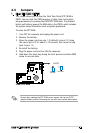
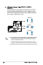
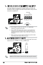
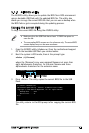
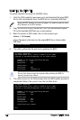
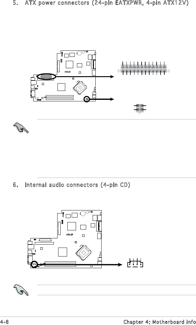
5. ATX power connectors (24-pin EATXPWR, 4-pin ATX12V)
These connectors are for ATX power supply plugs. The plugs from
the power supply are designed to t these connectors in only one
orientation. Find the proper orientation and push down rmly until the
connectors completely t.
R
ATX Power Connector
+12V DC
GND
+12V DC
GND
ATX12V
+3 Volts
+3 Volts
Ground
+5 Volts
+5 Volts
Ground
Ground
Power OK
+5V Standby
+12 Volts
-5 Volts
+5 Volts
+3 Volts
-12 Volts
Ground
Ground
Ground
PSON#
Ground
+5 Volts
+12 Volts
+3 Volts
+5 Volts
Ground
EATXPWR
•
Do not forget to connect the 4-pin ATX +12 V power plug;
otherwise, the system will not boot.
• Use of a PSU with a higher power output is recommended when
conguring a system with more power-consuming devices. The
system may become unstable or may not boot up if the power is
inadequate.
• Make sure that your power supply unit (PSU) can provide at least
the minimum power required by your system.
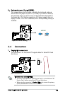
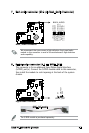
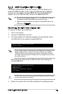
6. Internal audio connectors (4-pin CD)
These connectors allow you to receive stereo audio input from sound
sources such as a CD-ROM, TV tuner, or MPEG card.
Enable the CD-IN function in the audio utility when using this connector.
R
ATX Power Connector
CD
(black)
Right Audio Channel
Left Audio Channel
Ground
Ground