


ASUS P2E-M User’s Manual 31
III. INSTALLATION
Connectors
III. INSTALLATION
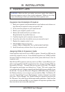
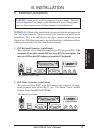
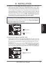
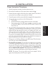
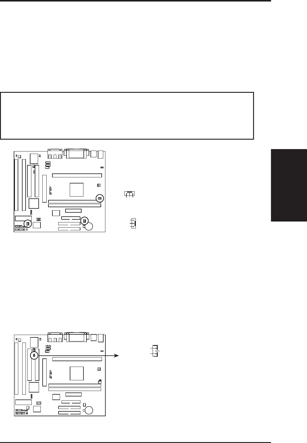
11. Chassis, CPU , & Power Supply Fan Connectors (3-pin CHA_, CPU_, PWR_FAN)
These connectors support cooling fans of 500mAMP (6 Watts) or less. Orien-
tate the fans so that the heat sink fins allow airflow to go across the onboard heat
sink(s) instead of the expansion slots. Depending on the fan manufacturer, the
wiring and plug may be different. The red wire should be positive, while the
black should be ground. Connect the fan’s plug to the board taking into consid-
eration the polarity of the this connector. NOTE: The “Rotation” signal is to
be used only by a specially designed fan with rotation signal.
WARNING! The CPU and/or motherboard will overheat if there is no airflow
across the CPU and onboard heatsinks. Damage may occur to the motherboard
and/or the CPU fan if these pins are incorrectly used. These are not jumpers,
do not place jumper caps over these pins.
P2E-M 12-Volt Cooling Fan Power
Chassis Fan Power
GND
Rotation
+12V
GND
Rotation
+12V
Power Supply Fan
CPU Fan Power
R
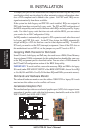
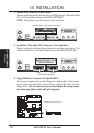
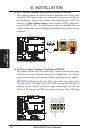
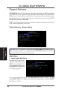
12. Wake On LAN Connector (3-pin WOL_CON)
These connector connects to LAN cards with a Wake On LAN output, such as the
ASUS PCI-L101 (see section VI. ASUS LAN Card). The connector powers up
the system when a wakeup packet or signal is received through the LAN card.
IMPORTANT: This feature requires that the WAKE On LAN Power Up Control is
set to Enabled (see “Power Management Setup” under IV. BIOS SOFTWARE) and
that your system has an ATX power supply with at least 720mA +5V standby power.
P2E-M Wake on LAN Connector
+5 Volt Standby
PME
Ground
R
IMPORTANT: Requires an ATX power
supply with at least 720mA +5-volt
standby power