


ASUS P2E-M User’s Manual 33
III. INSTALLATION
Connectors
III. INSTALLATION
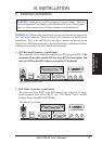
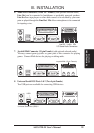
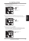
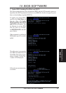
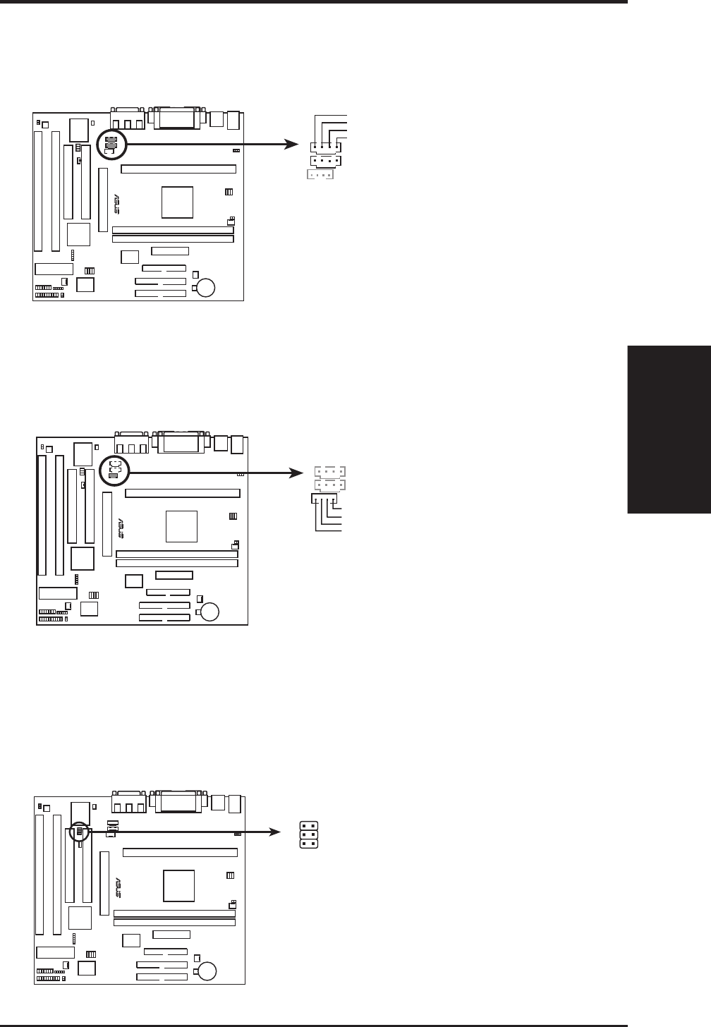
15. Stereo Audio In Connectors (4-pin AUX,CD1)
(with optional onboard audio)
These connectors allow you to receive stereo audio input from such sound sources
as a TV tuner or MPEG card.
R
Right Audio Channel
Left Audio Channel
Ground
Ground
P2E-M Stereo Audio In Connectors
AUX
CD1
NOTE: CD-1 has the same pin
definitions as AUX
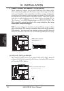
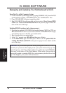
16. Stereo Audio In Connector (4-pin CD2) (with optional onboard audio)
This connector allows you to receive stereo audio input from an internal CD-
ROM drive.
R
Left Audio Channel
Right Audio Channel
Ground
Ground
P2E-M Stereo Audio In Connector
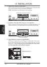
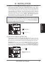
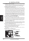
17. Digital Audio Interface (6-pin SPDIFO)
This connector is the digital link between the motherboard and your devices
such as CD player, sampler, or DAT recorder. It allows the digital transmission
of audio data in SPDIF (Sony/Philips Digital Interface) Format.
P2E-M Digital Audio Interface
R
TTL: Short this, if output device is TTL level
SPDIFO: Digital Signal OUT
SPDIFI: Digital Signal IN