


ASUS P2Z-VM User’s Manual 31
III. HARDWARE SETUP
Connectors
III. H/W SETUP
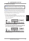
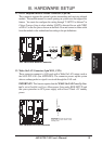
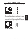
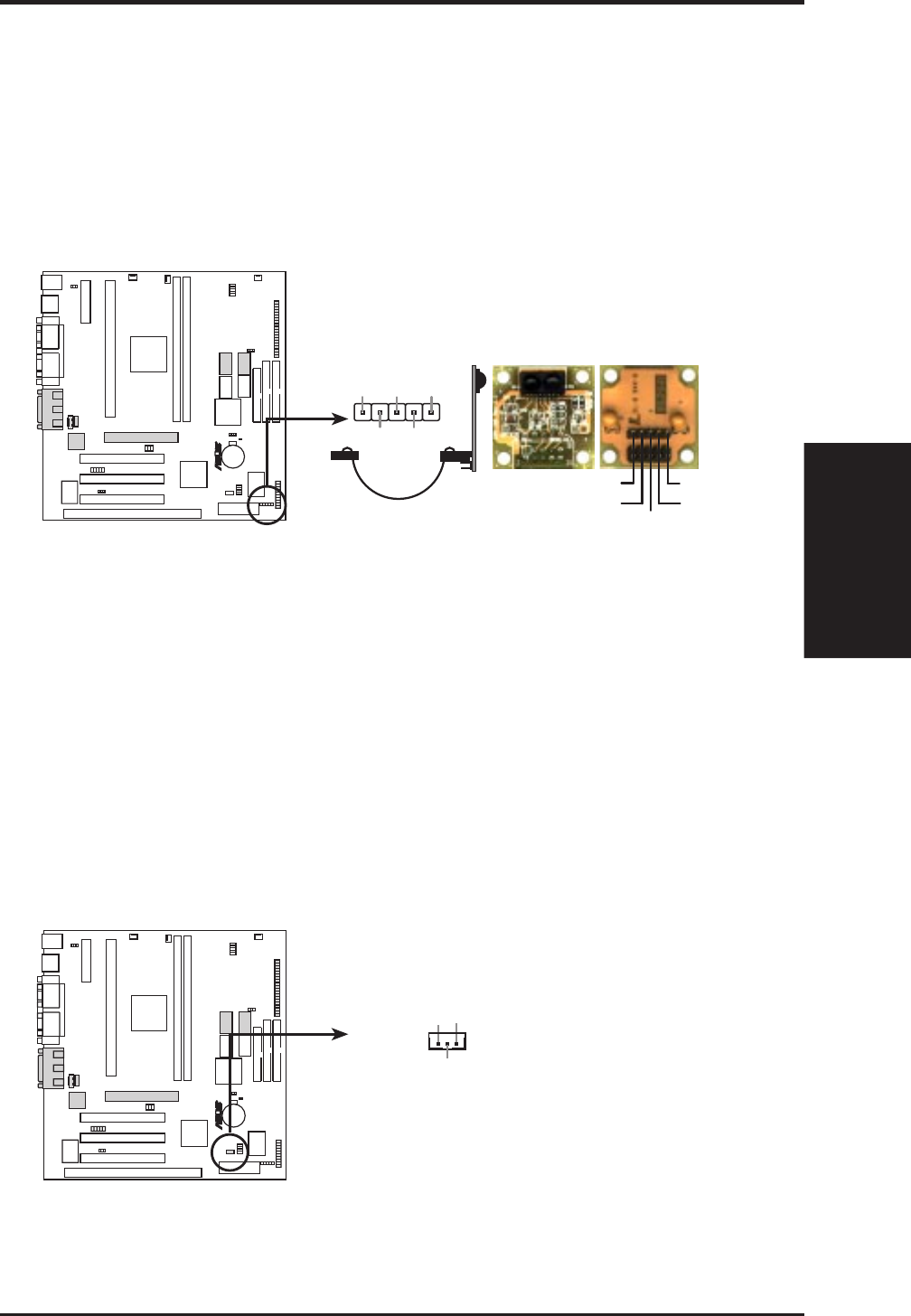
11. IrDA-Compliant Infrared Module Connector (5-pin IR)
This connector supports the optional wireless transmitting and receiving infrared
module. This module mounts to a small opening on system cases that support this
feature. You must also configure the setting through “UART2 Use Infrared” in
Chipset Features Setup to select whether UART2 is directed for use with COM2
or IrDA. Use the five pins as shown on the Back View and connect a ribbon cable
from the module to the motherboard according to the pin definitions.
P2Z-VM Infrared Module Connector
Front View
+5V
IRTX
IRRX
(NC)
GND
Back View
+5V
IRRX
IRTX
(NC)
GND
R
P2Z-VM
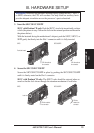
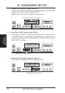
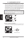
12. Wake-On-LAN Connector (3-pin WOL_CON)
These connector connects to LAN cards with a Wake On LAN output, such as
the ASUS PCI-L101 (See APPENDIX). The connector powers up the system
when a wakeup packet or signal is received through the LAN card.
IMPORTANT: This feature requires that the WAKE On LAN Power Up Con-
trol is set to Enabled (see Power Management Setup under BIOS SETUP) and
that your system has an ATX power supply with at least 720mA +5V standby
power.
P2Z-VM Wake-On-LAN Connector
IMPORTANT: Requires an ATX power
supply with at least 720mA +5Volt
standby power
+5 Volt Standby
PME
Ground
R
P2Z-VM