


32 ASUS P2Z-VM User’s Manual
III. HARDWARE SETUP
Connectors
III. H/W SETUP
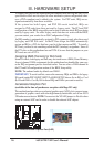
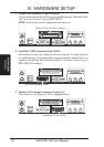
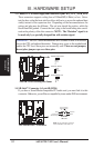
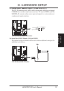
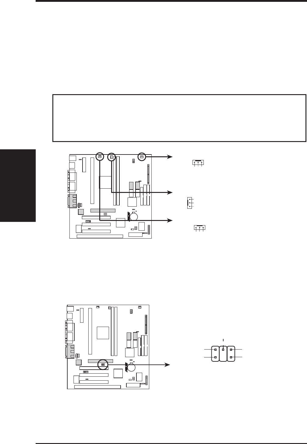
13. Chassis, CPU , & Power Supply Fan Connectors (3-pin CHA_, CPU_, PWR_FAN)
These connectors support cooling fans of 500mAMP (6 Watts) or less. Orien-
tate the fans so that the heat sink fins allow airflow to go across the onboard heat
sink(s) instead of the expansion slots. Depending on the fan manufacturer, the
wiring and plug may be different. The red wire should be positive, while the
black should be ground. Connect the fan’s plug to the board taking into consid-
eration the polarity of the this connector. NOTE: The “Rotation” signal is to
be used only by a specially designed fan with rotation signal.
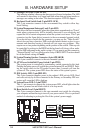
WARNING! The CPU and/or motherboard will overheat if there is no airflow
across the CPU and onboard heatsinks. Damage may occur to the motherboard
and/or the CPU fan if these pins are incorrectly used. These are not jumpers,
do not place jumper caps over these pins.
P2Z-VM 12-Volt Cooling Fan Power
Chassis Fan Power
Power Supply Fan
GND
Rotation
+12V
GND
Rotation
+12V
CPU Fan Power
GND
Rotation
+12V
R
P2Z-VM
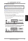
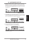
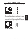
14. SB-Link™ Connector (6-1 pin SB-LINK)
If you have a Sound Blaster compatible PCI audio card, you must link it to this
connector. Otherwise, you will have compatibility issues under DOS environment.
NOTE: Pin 3 is removed to ensure the
correct orientation of the cable on it.
P2Z-VM SB-Link™ Connector
SB-LINK
PC/PCI Grant
Sideband Signal
5
6
PC/PCI Request
Sideband Signal
1
DGND
2
DGND
Serial IRQ
4
R
P2Z-VM