


ASUS P4B533-VM motherboard user guide
2-25
®
P4B533-VM
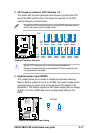
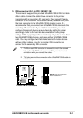
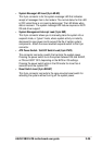
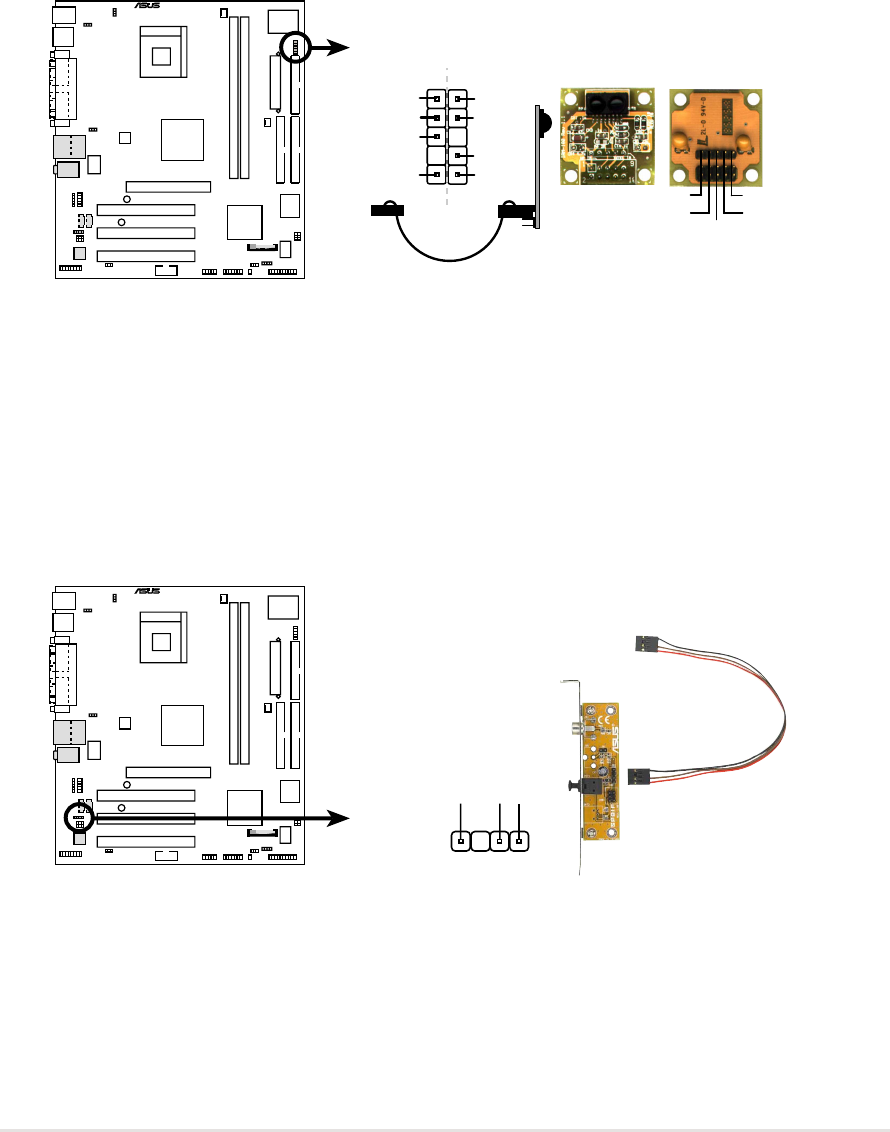
P4B533-VM Infrared Module Connector
Standard Infrared (SIR)
Front View Back View
+5V
IRTX
IRRX
(NC)
GND
SIR
+5V
IRRX
IRTX
GND
IRAX
GND
CIRRX
CIR+5V
CIR
®
P4B533-VM
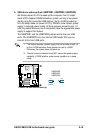
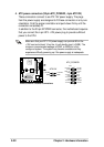
P4B533-VM Digital Audio Connector
+5V
SPDIFOUT
GND
SPDIF1
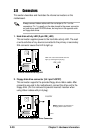
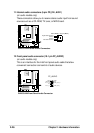
10. Digital audio connector (4-1 pin SPDIF1)
(on audio models only)
This connector is for an S/PDIF audio module that allows digital
instead of analog sound output. Connect one end of the audio cable to
the S/PDIF Out connector on the motherboard, and the other end to
the S/PDIF module.
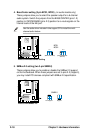
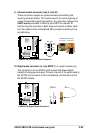
9. Infrared module connector (two 5-1 pin IR)
These connectors support an optional wireless transmitting and
receiving infrared module. The module mounts to a small opening on
system chassis that support this feature. You must also configure the
UART2 Use As parameter in BIOS to set UART2 for use with IR.
Use the five pins as shown in Back View and connect a ribbon cable
from the module to the motherboard SIR connector according to the
pin definitions.