


2-28
Chapter 2: Hardware information
®
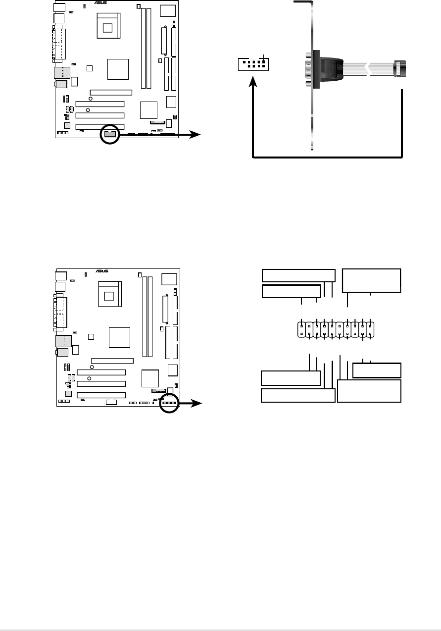
P4B533-VM
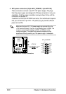
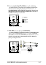
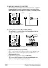
P4B533-VM System Panel Connectors
*
Requires an ATX power supply.
PLED
Ground
MLED
PWR
+5 V
Keylock
+5V
Speaker
Speaker
Connector
Power LED
Ground
+5 V
Reset SW
SMI Lead
Message LED
ExtSMI#
Ground
Reset
Ground
Ground
Ground
Keyboard Lock
ATX Power
Switch*
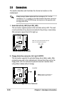
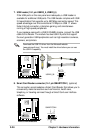
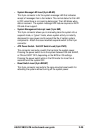
15. Serial port 2 connector (10-1 pin COM2)
This connector accommodates a second serial port using an optional
serial port bracket. Connect the bracket cable to this connector then
install the bracket into a slot opening at the back of the system chassis.
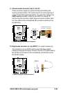
16. System panel connector (20-pin ASUS_PANEL1)
This connector is for various system front panel features. See the
description of each feature below.
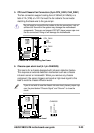
• System Power LED Lead (3-1 pin PLED)
This 3-1 pin connector connects to the system power LED. The LED
lights up when you turn on the system power, and blinks when the
system is in sleep mode.
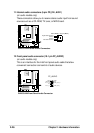
• System Warning Speaker Lead (4-pin SPEAKER)
This 4-pin connector connects to the case-mounted speaker and
allows you to hear system beeps and warnings.
®
P4B533-VM
P4B533-VM Serial COM2 Bracket
PIN 1
COM2