


1-8
Chapter 1: Product introduction
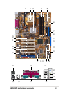
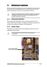
ATX 12V connector. This power connector connects the 4-pin 12V
plug from the ATX 12V power supply.
CPU socket. A 478-pin surface mount, Zero Insertion Force (ZIF)
socket for the Intel
®
Pentium
®
4 Processor, with 533/400 MHz system
bus that allows 4.3GB/s and 3.2GB/s data transfer rates, respectively.
North bridge controller. The Intel
®
845PE Memory Controller Hub
(MCH) provides the processor interface with 533/400 MHz frequency,
system memory interface at 333/266MHz operation, and 1.5V AGP
interface that supports AGP 2.0 specification including 4X Fast Write
protocol. The MCH interconnects to the south bridge ICH4 via the
Intel
®
proprietary Hub Interface.
DDR DIMM sockets. These three 184-pin DIMM sockets support up
to 2GB system memory using unbuffered non-ECC PC2700/
2100/1600 DDR DIMMs.
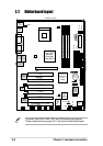
ASUS EZ Plug™ +12V connector. This ASUS patented auxilliary
power connector is used if you don’t have an ATX +12V power supply.
Connect a 4-pin device connector from a standard power supply to
this connector to provide sufficient power to the CPU.
ATX power connector. This 20-pin connector connects to an ATX
+12V power supply. The power supply must have at least 1A on the
+5V standby lead (+5VSB).
Floppy disk connector. This connector accommodates the provided
ribbon cable for the floppy disk drive. One side of the connector is
slotted to prevent incorrect insertion of the floppy disk cable.
IDE connectors. These dual-channel bus master IDE connectors
support Ultra DMA/100/66, PIO Modes 3 & 4 IDE devices. Both the
primary (blue) and secondary (black) connectors are slotted to prevent
incorrect insertion of the IDE ribbon cable.
RAID Ultra ATA/133/100 connector. This connector supports Ultra
ATA/133/100/66/33 HDD set to Master mode. Together with a Serial
ATA HDD on the SATA connector, the Master HDD on this Ultra
ATA133 connector may be configured as RAID 0 or RAID 1.
(on RAID models only)
9
8
7
6
5
4
3
2
1
1.4.2 Core specifications