


ASUS P4PE motherboard user guide
2-27
P4PE
®
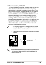
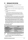
P4PE IEEE-1394 Connectors
IEEE1394_1
TPA0-
GND
TPB0-
+12V
GND
TPA0+
GND
TPB0+
+12V
1
TPA1-
GND
TPB1-
+12V
GND
TPA1+
GND
TPB1+
+12V
1
IEEE1394_2
P4PE
®
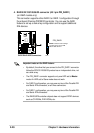
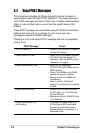
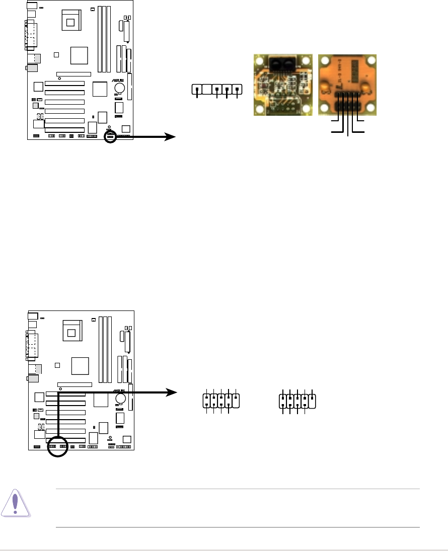
P4PE Infrared Module Connector
Back View
+5V
IRTX
IRRX
(NC)
GND
Front View
IR1
+5V
IRRX
IRTX
GND
1
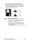
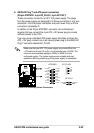
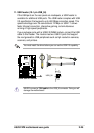
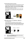
15. IEEE 1394 connectors (10-1 pin IEEE1394_1, IEEE1394_2)
(on 1394 models only)
These connectors are for the bundled 10-to-6-pin 1394 serial
connector cables that connect to the 1394 module. Attach the 10-1 pin
cable plugs to these connectors, and the 6-pin cable plugs to the 1394
module. You may also connect a 1394-compliant internal hard disk to
these connectors.
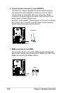
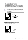
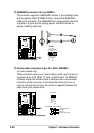
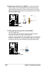
14. Infrared module connector (5-1 pin IR1)
This connector supports an optional wireless transmitting and receiving
infrared module. This module mounts to a small opening on system
chassis that support this feature. You must also configure the UART2
Use As parameter in BIOS to set UART2 for use with IR. See section
“4.4.2 I/O Device Configuration” for details.
Use the five pins as shown in Back View and connect a ribbon cable
from the module to the motherboard SIR connector according to the
pin definitions.
NEVER connect a USB cable to any of the IEEE 1394 connectors.
Doing so will damage the motherboard!