


ASUS P4S8X motherboard user guide
35
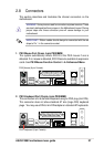
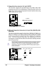
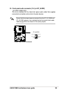
16. Digital audio connector (6 pin SPDIF) (optional)
This connector connects an S/PDIF audio module that allows digital
instead of analog sound output. Connect one end of the audio cable to
the S/PDIF Out connector on the motherboard, and the other end to the
S/PDIF module.
P4S8X
®
P4S8X Digital Audio Connector
SPDIF
GND
+5V
SPDIF_IN
SPDIF_OUT
GND
1
The S/PDIF module is not included in the motherboard package.
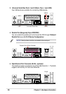
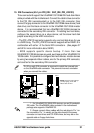
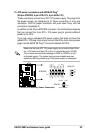
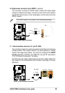
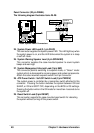
17. Infrared module connector (5-1 pin IR_CON)
This connector supports an optional wireless transmitting and receiving
infrared module. This module mounts to a small opening on system
chassis that support this feature. You must also configure the UART2
Use As parameter in BIOS to set UART2 for use with IR. See section
“4.4.2 I/O Device Configuration” for details.
Use the five pins as shown in Back View and connect a ribbon cable from
the module to the motherboard SIR connector according to the pin
definitions.
P4S8X
®
P4S8X Infrared Module Connector
Front View Back View
+5V
IRTX
IRRX
(NC)
GND
+5V
IRRX
IRTX
GND
IR_CON
1