


16
Chapter 2: Hardware information
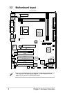
2.5 System memory
2.5.1 Overview
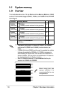
This motherboard has four 184-pin Rambus Inline Memory Modules (RIMM)
sockets. These sockets support 64Mbit, 128Mbit, and 256Mbit Direct RDRAM
technologies.
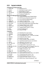
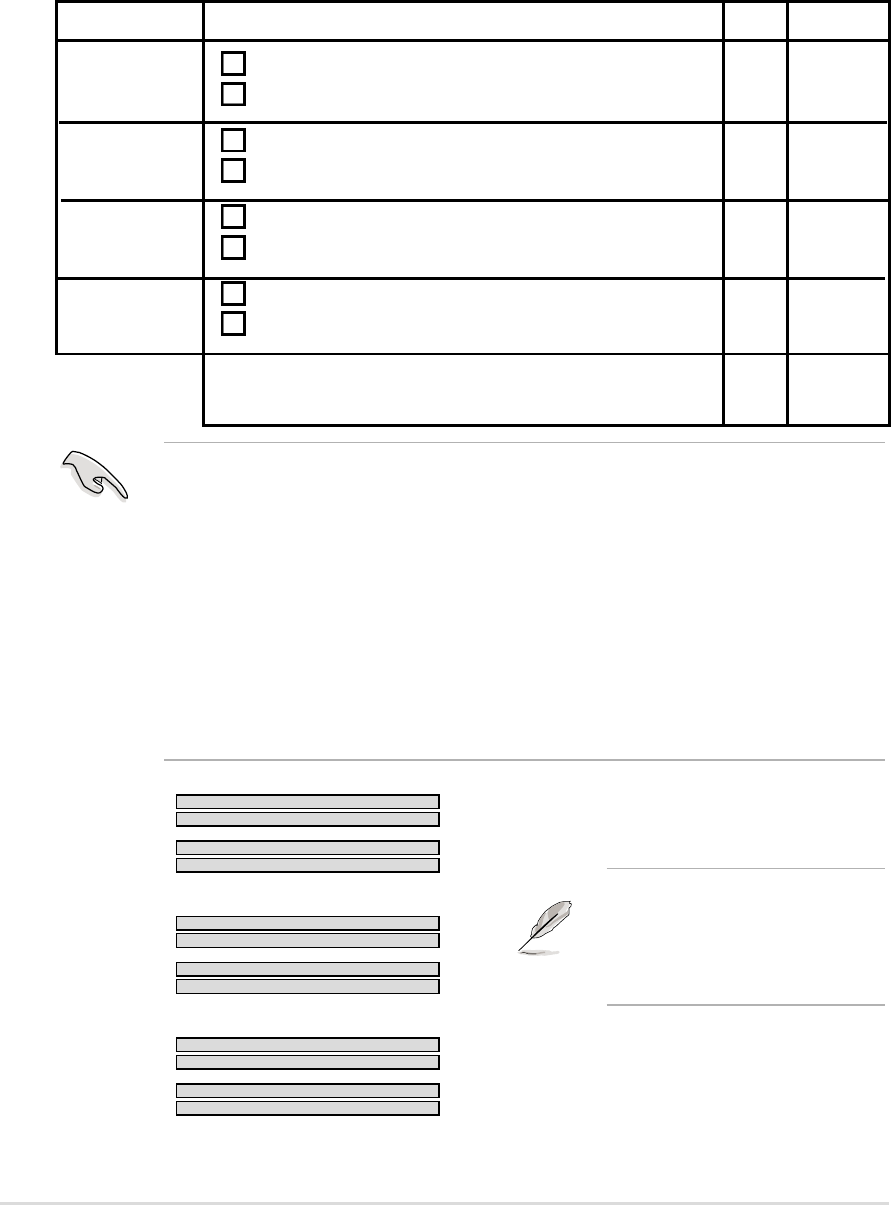
RIMMA1
RIMMA2
RIMMB1
RIMMB2
128MB RDRAM
128MB RDRAM
C-RIMM
C-RIMM
a.
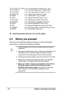
RIMMA1
RIMMA2
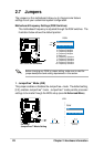
RIMMB1
RIMMB2
128MB RDRAM
128MB RDRAM
128MB RDRAM
128MB RDRAM
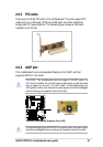
c.
RIMMA1
RIMMA2
RIMMB1
RIMMB2
128MB RDRAM
128MB RDRAM
C-RIMM
C-RIMM
b.
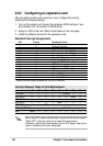
When using only two
memory modules, it is
recommended that you use
configuration a.
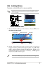
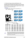
Location Memory Module Subtotal
RIMMA1
RDRAM x 1
(Rows 0&1)
C-RIMM
(use when socket will not be populated)
RIMMA2 RDRAM x 1
(Rows 2&3)
C-RIMM
(use when socket will not be populated)
RIMMB1 RDRAM x 1
(Rows 4&5)
C-RIMM
(use when socket will not be populated)
RIMMB2 RDRAM x 1
(Rows 6&7)
C-RIMM
(use when socket will not be populated)
TOTAL SYSTEM MEMORY =
(2GB Max)
• The memory configuration of channel A (RIMMA1 and RIMMA2)
and channel B (RIMMB1 and RIMMB2) must be identical (as
below).
• C-RIMMs (Continuity RIMM) must be used to complete the sockets
that are not populated by RDRAMs. A C-RIMM is necessary to
avoid breaking the signal lines, which are a serial connection in a
Rambus interface, such as used in this motherboard. This assures
the electrical integrity of a Rambus interface.
• When C-RIMMs are required, it is recommended that they be
inserted into RIMMA2 and RIMMB2.