


ASUS P4T-CM User’s Manual 33
3. HARDWARE SETUP
Connectors
3. H/W SETUP
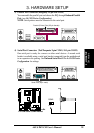
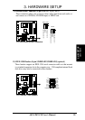
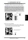
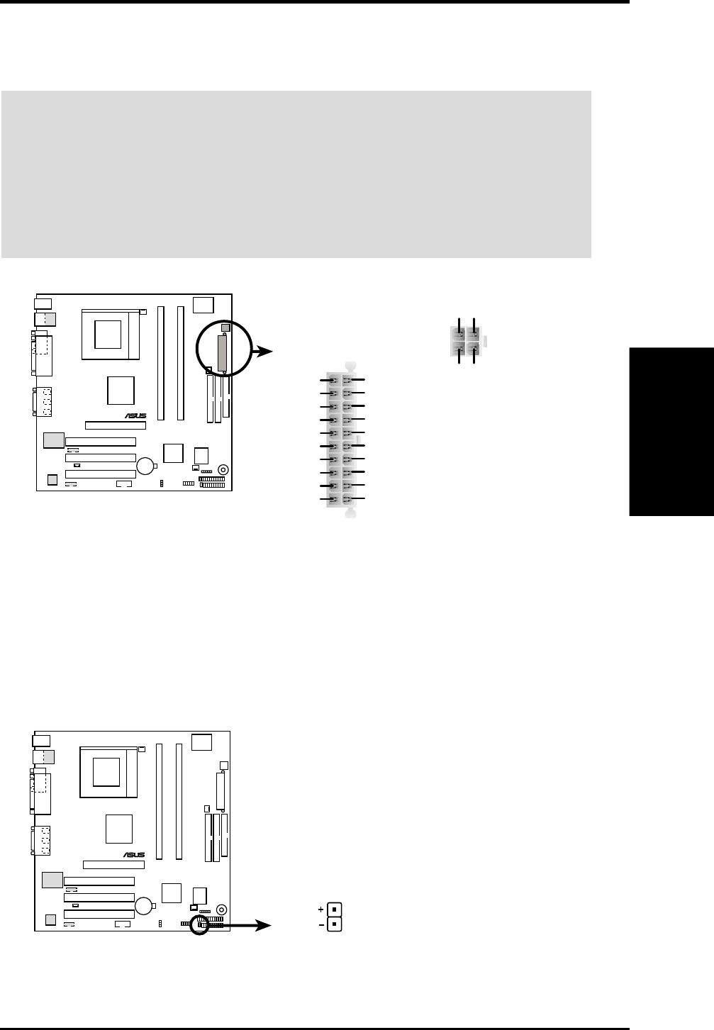
19) Power Supply Connectors (20-pin block ATXPWR) (4-pin ATX12V)
These connectors supply ATX 12V power. Each power supply plug inserts in
one orientation only. Push down firmly and make sure the pins are aligned.
IMPORTANT: Make sure that your ATX 12V power supply (minimum recom-
mended wattage: 230 watts; 300W for a fully-configured system) can supply at
least 20 amperes on the +5-volt lead and at least 720mA on the +5-volt standby
lead (+5VSB). Your system may become unstable/unreliable and may experi-
ence difficulty in powering up if your power supply is inadequate. For Wake-
On-LAN support, your ATX power supply (minimum recommended wattage:
230watts) must supply at least 720mA +5VSB.
P4T-CM
®
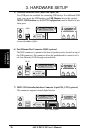
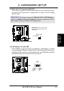
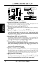
P4T-CM HD Activity LED
TIP: If the case-mounted LED does not
light, try reversing the 2-pin plug.
HDLED
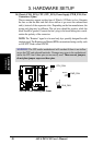
20) IDE Activity LED (2-pin HDLED)
This connector supplies power to the cabinet’s IDE activity LED. Read and
write activity by devices connected to the Primary/Secondary IDE and Primary/
Secondary ATA100 connectors will cause the LED to light up.
P4T-CM
®
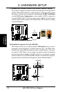
P4T-CM ATX &
Auxiliary Power Connectors
ATX12V
Pin 1
ATXPWR
+3.3VDC
-12.0VDC
COM
PS_ON#
COM
COM
COM
-5.0VDC
+5.0VDC
+5.0VDC
PWR_OK
+12.0VDC
+3.3VDC
+3.3VDC
COM
+5.0VDC
COM
+5.0VDC
COM
+5VSB
+12V DCCOM
+12V DCCOM
Pin 1