


P5KPL-AM SE
CHA_FAN
PCIEX16
PCIEX1_1
PCI1
PRI_IDE
USB56
USB78
AAFP
RTM870T-954
CD
ATX12V
EATXPWR
CPU_FAN
Intel
®
G31
Lithium Cell
CMOS Power
Super
I/O
ALC662
RTL
8102FL
8Mb
BIOS
SB_PWR
18.3cm(7.2in)
24.4cm(9.6in)
LGA775
Intel
®
ICH7
DDR2 DIMM_A1 (64bit, 240-pin module)
DDR2 DIMM_B1 (64bit, 240-pin module)
VGA
SATA2
SATA1
PS2_USBPW1-4
CLRTC
USBPW5-8
SPEAKER
AUDIO
KBMS
COM
LAN1_USB12
USB34
F_PANEL
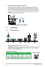
Place this side towards
the rear of the chassis.
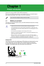
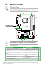
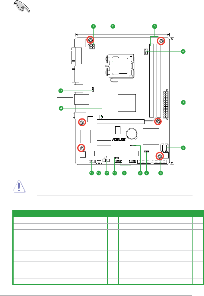
Place six screws into the holes indicated by circles to secure the motherboard to the
chassis. DO NOT overtighten the screws! Doing so can damage the motherboard.
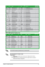
1.2.2 Layout contents
Connectors/Jumpers/Slots Page Connectors/Jumpers/Slots Page
1. ATX power connectors (24-pin EATXPWR, 4-pin ATX12V) 1-13 9. USB connectors (10-1 pin USB56, USB 78) 1-11
2. LGA775 socket
1-3 10. USB device wake-up (3-pin USBPW 5-8) 1-7
3. DDR2 DIMM slots
1-3 11. System panel connector (10-1 pin
F_PANEL)
1-14
4. CPU, CHA fan connectors (4-pin CPU_FAN, 3-pin
CHA_FAN)
1-12 12. Optical drive audio connector (4-pin CD) 1-14
5. Serial ATA connectors (7-pin SATA1, SATA2)
1-10 13. Front panel audio connector (10-1 pin
AAFP)
1-12
6. IDE connector (40-1 pin PRI_IDE)
1-11 14. Keyboard/mouse power (3-pin
PS2_USBPW1-4)
1-9
7. Clear RTC RAM (3-pin CLRTC)
1-8
8. Internal speaker connector (4-pin SPEAKER)
1-13
1.2 Motherboard overview
1.2.1 Motherboard layout
Ensure that you install the motherboard into the chassis in the correct orientation. The
edge with external ports goes to the rear part of the chassis.
Chapter 1: Product introduction 1-2