


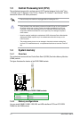
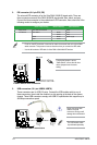
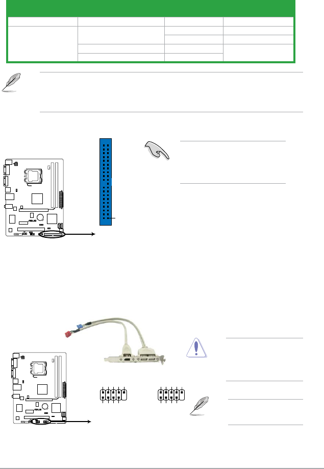
2. IDE connector (40-1 pin PRI_IDE)
The onboard IDE connector is for the Ultra DMA 100/66/33 signal cable. There are
three connectors on each Ultra DMA 100/66/33 signal cable: blue, black, and gray.
Connect the blue connector to the motherboard’s IDE connector, then select one of the
following modes to congure your device.
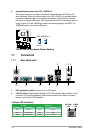
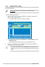
P5KPL-AM SE
PRI_IDE
NOTE:Orient the red markings
on the IDE ribbon cable to PIN 1.
PIN1
P5KPL-AM SE IDE connector
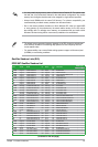
Driver Jumper setting Mode of device(s) Cable connector
Single device Cable-Selected or Master - Black
Two devices Cable-Select Master Black
Slave Gray
Master Master Black or gray
Slave Slave
• Pin 20 on the IDE connector is removed to match the covered hole on the Ultra DMA
cable connector. This prevents incorrect insertion when you connect the IDE cable.
• Use the 80-conductor IDE cable for Ultra DMA 133/100/66 IDE devices.
If any device jumper is set as
“Cable-Select,” ensure that all other
device jumpers have the same
setting.
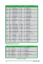
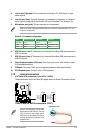
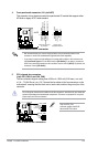
3. USB connectors (10-1 pin USB56, USB78)
These connectors are for USB 2.0 ports. Connect the USB module cable to any of
these connectors, then install the module to a slot opening at the back of the system
chassis. These USB connectors comply with USB 2.0 specication that supports up to
480 Mbps connection speed.
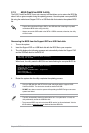
PIN 1
USB+5V
USB_P8-
USB_P8+
GND
NC
USB+5V
USB_P7-
USB_P7+
GND
USB78
PIN 1
USB+5V
USB_P6-
USB_P6+
GND
NC
USB+5V
USB_P5-
USB_P5+
GND
USB56
P5KPL-AM SE
P5KPL-AM SE USB2.0 connectors
Never connect a 1394
cable to the USB
connectors. Doing so will
damage the motherboard!
The USB module cable
is purchased separately.
1-11 ASUS P5KPL-AM SE